Saturday, 17 November 2012

Calibration Complete

Well,

Following my musings back here:

http://g0mgx.blogspot.co.uk/2012/11/the-art-of-calibration.html

about making some known RF sources, I seem to have been successful. I have created a -20dBm and -50dBm RF source which I have used to calibrate my bench power meter:


As well as the two RF sources I've also made two pads in little die-cast boxes; one of 20dB and one of 30dB.

This should provide me with the tools I need for power measurement and calibration.

Good, egh?


The Art of Calibration

Well,

Been thinking some more about power meters and the calibration of them. Quite tricky really, as you need an known RF source to calibrate a meter against it, but to have an accurate and known RF source, you need a calibrated meter to measure it. Recursion: see recursion.

The first thing I have done is to build a power meter that was published in QST, it's designed by Roger Hayward, KA7EXM and is PIC based. This is a stand alone meter for simply measuring from about -80dBm to +7dBm:


Then to calibrate this baby the text says... "assume for a moment that you have an accurate signal generator capable of -70dBm to +7dBm"..... well I don't!

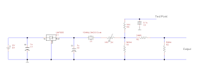
So, a newly found homebrew chum in VK land pointed me at an article by Bob Kopski, K3NHI where he presents a simple calibration source using a CMOS clock oscillator. It kind of looks like this:

So the idea here is that you set the variable resistor such that a digital volt meter connected to the test point reads exactly 158mV. Then in the example above the output goes through a attenuator pad such that the output port is a known -20dBm signal at 10MHz. As I need at least two reference points to calibrate anything (because of the interpolation needed in software) I figured I could use a different pad at the output to create another one of these at, say, -30dBm or even -50dBm. Here's one of them on the bench under test:


Creating a pad is quite simple and there are a number of calculators on the Internet, here's the one I used:

http://chemandy.com/calculators/pi-attenuator-calculator.htm

I'm one BNC socket short of the party right now, so I'll post more to let you know how I get on, but here's one of them in a box ready for use:

Fun, egh?

Thursday, 15 November 2012

Over the pond on Top Band

Well,

You may recall my ramblings about Top Band back here:

http://g0mgx.blogspot.co.uk/2012/08/well-this-top-band-twig-does-it-work.html

So on-and-off I've been leaving WSRP running on either Top Bank or 30M over night, just to see how far signals are getting, and have been wondering if this may ever happen:


Well, looks like it has!

Fun, egh?

Monday, 12 November 2012

My Power Struggle is Over

Well,

Following all the palaver associated with my Power Meter project; I've finally completed it.

Here's the finished article:


The front panel (which is covered in Fablon) isn't anything like as bumpy as it looks in the photo to the naked eye; it's perfectly acceptable.

I've finally decided that the switches need to switch between short and long sample times (as before) but the second switch that I had used to peak hold the meter, now switches the units primary display units from dbM to dbW - each of these has the power converted to watts in brackets.

The unit had quite a bit of use this weekend in the WAE RTTY contest - and yes I was sending and receiving QTC traffic! - but the meter certainly seems to work at full UK power from my linear, it's a damn site more accurate than anything else I have here, but most impressive was the ability of the unit to read really low reflected powers so I can tune the antenna far better with this unit than I can with any of the analogue meters I have here. This meter can tell be that I have -20dbW reflected power when an analogue meter wont even be moving.... I'm actually quite impressed.

Cat's not overly enthusiastic about it:

Impressive though, egh?


Saturday, 3 November 2012

Scaling the heights of power

Well,

Having finally got a working digital and software based power meter, I have been running some experiments today - already this is proving to be a useful instrument. I think it might be worth making an alternative version of the system to be a stand alone power meter (rather than a directional meter with SWR calcs). However, the main enhancement today has been the inclusion of a (rather humorous) meter scale for the analog SWR meter:


All I did was remove the metal scale that came with the meter, scan it into the computer and then use MS Paint to alter it. I've printed it and stuck it to the old one with "pritt stick". Looks kind of fine to me:


The instrument display is looking pretty good too:


There are two switches on the front panel (as per the W7IEQ design). So I've modified the software to either sample the RF in a short mode or a longer, more time between samples mode. Hence you can see "Sht" for "Short" - this changes to "Lng" or "Long" when the 1st switch is set. Similarly I've added some code to peak hold the meter and this can be turned on with the second switch; the display shows "Norm" or "Hold".

I need to do something better with the front panel of the case and also I'd like to illuminate the meter.


Not bad though, egh?
 

Friday, 2 November 2012

The Power is with me...

Well,

After all the antics with this power meter project, I've finally got a working project; however, not quite through the route you would imagine.

Having spent even more time studying the assembler code for the W7IEQ power meter, and realising that I would need to change all of the vast lookup tables used to convert the AtoD readings into dbM, I then found something in the code comments that made my heart nearly stop...

"This routine uses a packed 16-bit floating point value that I developed to reduce memory usage in a look-up table relating power in watts to measured ADC values for forward and reflected powers.

The packed values contain a 10-bit "reduced" mantissa (m) and a 6 bit shifted exponent (s).  All values are assumed positive so there is no need for a sign bit. Also, the first bit in the mantissa, which is always 1 except when the number id 0, is suppressed.  The offset value for the exponent is 27. A shifted exponent of 0 means the number is 0."

So I very rapidly concluded that I stood little or no chance of getting to grips with this in a hurry, and I was close to despair already with this anyhow!

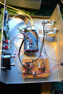
So, here's what I did.... Firstly I ripped the main board out of the box and threw it in the bin. Then I replicated the Sample and Hold op-amp circuitry plus the amp used to drive the meter on some veroboard. This board plus an Arduino

www.arduino.cc

board I had were introduced into the box....


So, I have the original AD8307 boards, but everything else has been replaced. I opened a blank arduino "sketch" (or project) and started from scratch to write the code....

Because the Arduino code is written in a high level language and there are very few memory or other limitations on the board itself, the code doesn't need to be especially well optimised for speed or size. Also the high level language and the library routines that come out of the box mean that all the "tricky" bits associated with reading the AtoD or setting the PWM et cetera are already available for use - so the software is really quite easy to write and also easy to read and modify by other people.

Here's a link to the code:

http://www.qsl.net/g/g0mgx//BlogFiles/power_meter.ino

and also the spreadsheet that I made to calibrate it:

http://www.qsl.net/g/g0mgx//BlogFiles/Power%20Meter%20Calibration%20Arduino.xlsx

So the LCD display is currently set up to display the forward and reflected power in Watts and dbM plus the calculated SWR. The SWR is also indicated on the meter.

The code took an evening to start and then about 6 hours to complete going with my ever favoured method of write a bit, test a bit.


There's lots left still to do, like a front panel and a meter scale. I will also introduce the concept of average power readings and things like that. But I think I need to see the unit in use before I can decide exactly how I want it to behave.

Cat's not impressed:

Good though, egh?