Friday, 21 December 2012

DDSing once more

Well,

I've been out of the country for a while; been working in the US of A. Great place, visited Chicago, Pittsburgh and Houston this trip - got myself some great boots!

Today I have broken up for Christmas and am looking forward to some good time at home with family, friends and, of course, my hobbies!

I've been fiddling today with the DDS signal generator I made here:

http://g0mgx.blogspot.co.uk/2012/02/dds-running-well.html

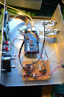
And would like to improve the design a little. It would be good to follow the DDS with a broadband RF amplifier, perhaps the one I used here would be a good starting point:

http://g0mgx.blogspot.co.uk/2012/06/its-been-ages.html

Who knows? I would also like to add a stepped output attenuator that's controlled by software and also feedback the RF output to one of the Analogue inputs of the Arduino so I can have a dbM display on the LCD, much like the separate meter I made recently:

http://g0mgx.blogspot.co.uk/2012/11/calibration-complete.html

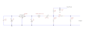
So, my starting point was to replicate the existing project and then add the AD8307 logarithmic amplifier circuitry:


So here we are again, another project is born.

I'll keep you posted, fun though, egh?

Saturday, 17 November 2012

Calibration Complete

Well,

Following my musings back here:

http://g0mgx.blogspot.co.uk/2012/11/the-art-of-calibration.html

about making some known RF sources, I seem to have been successful. I have created a -20dBm and -50dBm RF source which I have used to calibrate my bench power meter:


As well as the two RF sources I've also made two pads in little die-cast boxes; one of 20dB and one of 30dB.

This should provide me with the tools I need for power measurement and calibration.

Good, egh?


The Art of Calibration

Well,

Been thinking some more about power meters and the calibration of them. Quite tricky really, as you need an known RF source to calibrate a meter against it, but to have an accurate and known RF source, you need a calibrated meter to measure it. Recursion: see recursion.

The first thing I have done is to build a power meter that was published in QST, it's designed by Roger Hayward, KA7EXM and is PIC based. This is a stand alone meter for simply measuring from about -80dBm to +7dBm:


Then to calibrate this baby the text says... "assume for a moment that you have an accurate signal generator capable of -70dBm to +7dBm"..... well I don't!

So, a newly found homebrew chum in VK land pointed me at an article by Bob Kopski, K3NHI where he presents a simple calibration source using a CMOS clock oscillator. It kind of looks like this:

So the idea here is that you set the variable resistor such that a digital volt meter connected to the test point reads exactly 158mV. Then in the example above the output goes through a attenuator pad such that the output port is a known -20dBm signal at 10MHz. As I need at least two reference points to calibrate anything (because of the interpolation needed in software) I figured I could use a different pad at the output to create another one of these at, say, -30dBm or even -50dBm. Here's one of them on the bench under test:


Creating a pad is quite simple and there are a number of calculators on the Internet, here's the one I used:

http://chemandy.com/calculators/pi-attenuator-calculator.htm

I'm one BNC socket short of the party right now, so I'll post more to let you know how I get on, but here's one of them in a box ready for use:

Fun, egh?

Thursday, 15 November 2012

Over the pond on Top Band

Well,

You may recall my ramblings about Top Band back here:

http://g0mgx.blogspot.co.uk/2012/08/well-this-top-band-twig-does-it-work.html

So on-and-off I've been leaving WSRP running on either Top Bank or 30M over night, just to see how far signals are getting, and have been wondering if this may ever happen:


Well, looks like it has!

Fun, egh?

Monday, 12 November 2012

My Power Struggle is Over

Well,

Following all the palaver associated with my Power Meter project; I've finally completed it.

Here's the finished article:


The front panel (which is covered in Fablon) isn't anything like as bumpy as it looks in the photo to the naked eye; it's perfectly acceptable.

I've finally decided that the switches need to switch between short and long sample times (as before) but the second switch that I had used to peak hold the meter, now switches the units primary display units from dbM to dbW - each of these has the power converted to watts in brackets.

The unit had quite a bit of use this weekend in the WAE RTTY contest - and yes I was sending and receiving QTC traffic! - but the meter certainly seems to work at full UK power from my linear, it's a damn site more accurate than anything else I have here, but most impressive was the ability of the unit to read really low reflected powers so I can tune the antenna far better with this unit than I can with any of the analogue meters I have here. This meter can tell be that I have -20dbW reflected power when an analogue meter wont even be moving.... I'm actually quite impressed.

Cat's not overly enthusiastic about it:

Impressive though, egh?


Saturday, 3 November 2012

Scaling the heights of power

Well,

Having finally got a working digital and software based power meter, I have been running some experiments today - already this is proving to be a useful instrument. I think it might be worth making an alternative version of the system to be a stand alone power meter (rather than a directional meter with SWR calcs). However, the main enhancement today has been the inclusion of a (rather humorous) meter scale for the analog SWR meter:


All I did was remove the metal scale that came with the meter, scan it into the computer and then use MS Paint to alter it. I've printed it and stuck it to the old one with "pritt stick". Looks kind of fine to me:


The instrument display is looking pretty good too:


There are two switches on the front panel (as per the W7IEQ design). So I've modified the software to either sample the RF in a short mode or a longer, more time between samples mode. Hence you can see "Sht" for "Short" - this changes to "Lng" or "Long" when the 1st switch is set. Similarly I've added some code to peak hold the meter and this can be turned on with the second switch; the display shows "Norm" or "Hold".

I need to do something better with the front panel of the case and also I'd like to illuminate the meter.


Not bad though, egh?
 

Friday, 2 November 2012

The Power is with me...

Well,

After all the antics with this power meter project, I've finally got a working project; however, not quite through the route you would imagine.

Having spent even more time studying the assembler code for the W7IEQ power meter, and realising that I would need to change all of the vast lookup tables used to convert the AtoD readings into dbM, I then found something in the code comments that made my heart nearly stop...

"This routine uses a packed 16-bit floating point value that I developed to reduce memory usage in a look-up table relating power in watts to measured ADC values for forward and reflected powers.

The packed values contain a 10-bit "reduced" mantissa (m) and a 6 bit shifted exponent (s).  All values are assumed positive so there is no need for a sign bit. Also, the first bit in the mantissa, which is always 1 except when the number id 0, is suppressed.  The offset value for the exponent is 27. A shifted exponent of 0 means the number is 0."

So I very rapidly concluded that I stood little or no chance of getting to grips with this in a hurry, and I was close to despair already with this anyhow!

So, here's what I did.... Firstly I ripped the main board out of the box and threw it in the bin. Then I replicated the Sample and Hold op-amp circuitry plus the amp used to drive the meter on some veroboard. This board plus an Arduino

www.arduino.cc

board I had were introduced into the box....


So, I have the original AD8307 boards, but everything else has been replaced. I opened a blank arduino "sketch" (or project) and started from scratch to write the code....

Because the Arduino code is written in a high level language and there are very few memory or other limitations on the board itself, the code doesn't need to be especially well optimised for speed or size. Also the high level language and the library routines that come out of the box mean that all the "tricky" bits associated with reading the AtoD or setting the PWM et cetera are already available for use - so the software is really quite easy to write and also easy to read and modify by other people.

Here's a link to the code:

http://www.qsl.net/g/g0mgx//BlogFiles/power_meter.ino

and also the spreadsheet that I made to calibrate it:

http://www.qsl.net/g/g0mgx//BlogFiles/Power%20Meter%20Calibration%20Arduino.xlsx

So the LCD display is currently set up to display the forward and reflected power in Watts and dbM plus the calculated SWR. The SWR is also indicated on the meter.

The code took an evening to start and then about 6 hours to complete going with my ever favoured method of write a bit, test a bit.


There's lots left still to do, like a front panel and a meter scale. I will also introduce the concept of average power readings and things like that. But I think I need to see the unit in use before I can decide exactly how I want it to behave.

Cat's not impressed:

Good though, egh?

Wednesday, 31 October 2012

Feel the Power!

Well,

Since the progress I discussed last time:

http://g0mgx.blogspot.co.uk/2012/10/its-becoming-real-power-struggle.html

with this power meter project; I've had (yet another) build of the directional coupler:


This time its been constructed from double sided PCB material and uses FT-82-67 toriods.

Connecting the forward and reflected ports to my 'scope (terminated with 50R) with a RF generator (this one is made my Kenwood) connected to the transmitter port and a dummy load connected to the antenna port, here's what I found on the 'scope (I've got the setup wrong and the blue reflected port reading on the 'scope needs to be divided by 10):


I then connected the coupler to the ports on the power meter and also included a 30dB attenuator. The attenuator was constructed using this site here as a Pi attenuator:

http://www.microwaves101.com/encyclopedia/calcattenuator.cfm

The setup for the next phase looks very much like this:

 
So, once this was put together, I then constructed an excel table with frequency across the top and the AtoD down the side, this table looks like this for the forward port of the coupler:


So, once I had these values I can the look into the equation that will take me from the A-to-D reading back to power - this is basically what the power meter needs to do - here's the equation:


So solving this equation as a pair of simultaneous equations - in fact a pair or more of simultaneous equations - I see this:

and this:


so basically I get different constants depending on what lines of the table I use as the input to my simultaneous equations.

However, despite the different constants, if I then use the equation and the constants to re-generate my powers from the ADC values the curve seems to be a very good fit. Here is the original readings plus the two equation outputs plotted:


So, all in all, I'm rather confused about the whole thing! But whatever the confusion, the device certainly seems to be very frequency stable i.e. very little variation in AtoD values as frequency increases. It's all good.

The software I have for this meter contains a huge set of lookup tables for the AtoD reading to power conversion; clearly these all need to change!

Cat's not helped much:


 All good though egh? I'd love to know what you think.

Sunday, 28 October 2012

It's Becoming a Real Power Struggle

Well, blimey!

How hard can it be to get a piece of PIC assembler software to display some characters on an LCD display? The answer seems to be very.

I've started putting my power meter together, it's the one I started here:

http://g0mgx.blogspot.co.uk/2012/10/a-bit-of-power-struggle.html

Well, eventually I managed to assemble all the parts and put the boards into an enclosure I have here:


I've actually made quite a good job of the metalwork so far, I've intentionally not cut the hole for the display as I don't yet know which one of the many I have here I would end up using. Here's the view of the front panel as-is now, the meter looks OK but isn't the large meter I found, as that's just too big for the case!


So, PIC programmed, LCD display wired in, power on - nothing. Just some very faint black squares on the display that I can make more evident or go away using the on-board contrast control.

So, still not knowing if the software is intended to interface to an HD4470 compatible or not, the question was what to try next?

I ended up cutting the software back to just the display routines and simply programming the PIC with the code to display just a few characters on the LCD. Result - nothing.

So, next I added a simple loop at the end of the LCD routine calls to turn on and off one of the digital output ports every second. I attached a suitable LED to the port and tried again - as expected the LED started to flash. This told me a few things:

  • My PIC programming was working and my software was making it into the chip;
  • The software was reaching my loop for LED flashing so it wasn't getting stuck anywhere;
  • The routines for the LCD weren't working.
Now, you may (or may not) recall I did quite a bit of fiddling with LCD displays and Pinguino and more recently Arduino back here:

http://g0mgx.blogspot.co.uk/2012/02/four-isnt-quite-same-as-2.html

So from that messing about I had a reasonably good idea how the initialisation of these LCDs should look, and the code I was staring at didn't quite look the same. So I changed the sequence of numbers sent to the LCD to initialise it, re-programmed the PIC and tried again. Nothing.

Hmm, next I looked at the delays in the software between writing the Enable line on the LCD high and then low again - you kind of have to do an "open sesame" on the LCD every time you send it either data or a command and the delays in the assembly software I was looking at used the processor "nop" instruction. This is really a null operand and hence takes one (I think) clock tick to execute. I changed this to be a 1ms delay and.... Bingo! We have characters on the display:


So, my next puzzle was the fact that I could display the characters 0-9 OK, but any attempt at alpha characters resulted in, what looked very much like, Japanese characters appearing on the display. After much cursing, general muttering and many re-programming of the PIC to try different things, I found a short between two of the address lines on the board. Doh! It took me over 6 hours to find that as I was only looking in software....

So it does seem that I am moving in the correct direction. I have also found that the Assembly code I downloaded from the QST in-depth website for this project, doesn't assemble on my version of MPLAB. I've had to change a few things:

  • declared names are clearly case sensitive in my assembler and not used in that way in the code - many capitalisation changed;
  • literal values used with the "loadw" command - the decimal declarations used generated value too big warnings, all I have done is declare the values as the hex equivalent and prefixed with "0x" - I don't understand why this is different, but it assembles;
  • The declared names in the .inc file for the processor are also case sensitive so again, a number of changes needed there.
I then incorporated my changes to the display routines into the downloaded software and now I am seeing what I expected to see on the display.....

It's time to test the unit, I'll let you know how I get on. I suspect I need to re-make the directional coupler (again) as I posted a photo on the eHam.net homebrew forum and asked for some advice, here's a very polite post telling me what a pile of junk I have made:

eHam comments

Hard work, frustrating but all good though, egh?


Tuesday, 23 October 2012

A Bit More of a Power Struggle

Well,

What a palavar! You remember the Power Meter project from here:

http://g0mgx.blogspot.co.uk/2012/10/i-wonder-how-much-power-is-there.html

and here:

http://g0mgx.blogspot.co.uk/2012/10/a-bit-of-power-struggle.html

well, I ordered the strange surface mount resistors I needed that were 52.3 ohms from Farnel. They have a £20 minimum order value so I bought all sorts of other stuff that I didn't really need; they arrived today and I have completely goofed over the type I have ordered. The ones that arrived today are so small, you need a magnifying glass to even see the component on a white piece of paper! They are less than 0.5mm long - no use to me and my soldering iron at all!

I've nearly finished the power supply for the project today and the main board is also now fully populated - the PSU just needs a mains input on the back:


The power supply is in a case I found in a really neat shop in the centre of Derby called RF Potts; they sell all sorts of great electronic bits and bobs in there; so this Verobox was £1.90 (so I bought 5!):


Here's the main board:


So, progress is slow and steady! I've emailed the project designer today to ask what type the LCD display needs to be - I'm sure it'll be a HD4470 compatible, but it would be nice to know for sure - the less unknowns in these scenarios the better!

Looking good though, egh?

Sunday, 21 October 2012

JARTS - You What? Oh, JARTS

Well,

Had a little dabble in the JARTS RTTY contest today and yesterday, conditions seemed to be really good, but there wasn't as much activity as I had hoped for. Here's my log from the contest in map format:


There were a few new countries for me, but NOTHING in Africa at all! And also no VK (Australia) or ZL (New Zealand) but hey, ho, it was fun all the same!
Still, rather impressive, egh?


A Bit of a Power Struggle

Well,

You may remember that I started a Power/SWR meter project back here:

http://g0mgx.blogspot.co.uk/2012/10/i-wonder-how-much-power-is-there.html

as I said then, I had ordered the circuit boards for the project from Far Circuits, and they have duly arrived.

Unfortunately, I am a few bits short of a full kit within my vast collection of components, and have had to order a couple of SMT components (52.3R resistors!) and a 2.5V reference plus a couple of other small parts.

I should be able to complete the project when those bits arrive; I'm also struggling to figure out if the display used is a HD4470 compatible device, or something else completely. I cant actually find a way to figure that out.

The boards look like this so far:

The two smaller boards underneath the meter are the A to D converters, these take the voltage out of the directional coupler I made in the last post and convert it to a digital data stream; the devices used are Analogue Devices 8307 and they are logarithmic. The main board is at the bottom of the photo on the left hand side and the PSU is at the bottom right.

The meter you can see is really neat; this was an eBay purchase, although it's bigger than I anticipated (it's actually exactly the size the seller said it was but I didn't bother reading it). So I may need to rummage for something suitable to enclose this project when its complete as I haven't got anything here bog enough to house the meter neatly - I do have a smaller meter of the correct value so I may end up using that.

Cats been helping again:


I'll post more when the missing pieces of the jigsaw arrive.

Good though, egh?

Sunday, 14 October 2012

I wonder how much power is there?

Well,

Since I got my linear amplifier that I told you about here:

http://g0mgx.blogspot.co.uk/2012/09/how-much-power.html

I've been wondering about power measurement. Now, I have the power meter on the linear, a power meter made by Diawa, one made by some other manufacturer.... the point being that they all read different values for the same output!

So, this got me wondering about how to really measure power.

So, in simple terms if we measure the Peak-to-Peak voltage of a waveform, we need to calculate the RMS voltage by:

(P-to-P / 2) * (Sqrt (2) / 2) which is:

(P-to-P / 2) * 0.707

So, for example, lets say we have 100 V peak-to-peak, thats the same as 35.35 V RMS.

Now, to get power in Watts we need to:

(V RMS ^ 2) / R where R is the load impedance (in my case nearly always 50 ohms)

So, my 100V P-to-P or 35.35V RMS is:

(35.35 ^ 2) / 50

which is equal to, or as near as damn it, 25 Watts.

So, making a simple plot of P-to-P vs. RMS vs. Power (Watts) is quite simple, and it looks like this:


So, hopefully you will be able to see that the range of power or voltage we plot doesn't matter, the line will always be the same shape.

So, theory says, that if I connect an RF generator (perhaps one made by Yaesu) to a dummy load, then connect my x10 scope probe across the dummy load, I should be able to measure an accurate P-to-P voltage and quickly calculate the Power in Watts. This didn't seem to be the case when I tried it.

I used the FT-857 I have here and set it to its 20 Watt output setting, I was reading about 124V P-to-P which is more like 38 Watts, whilst I expected the radio setting to be an approximation, I never expected it to be this far out!

So, another experiment was called for. This time I connected the 'scope in the same way, but plotted different power and frequencies. Here is what I found:


You will notice that the reading for 40 Watts at 50 MHz is missing from the graph above. Just as I applied the power was exactly the start of the smoke emanating from the 'scope probe. That probe is RIP.

Now, whilst I don't claim to understand why, it is clear from the measurements above that at low power & low frequency my measurements are close to as expected. As the power increases and certainly as the frequency increases then the measurements become wildly inaccurate!

So, this made me rummage on the interweb for some kind of accurate power measurement project. This is what I found:
 
http://www.arrl.org/files/file/Product%20Notes/2012%20Handbook/KAUNE.pdf

Now this looks like just the ticket!

So, today I have started to make the directional coupler - this is the bit that sniffs the RF in a feeder and produces a forward and reflected waveform... mine looks like this:


Far Circuits in the USA:

http://www.farcircuits.net/

do the circuit boards for this power meter project so I've ordered a set. I've bought from them before and the service is usually excellent. So, when I have the boards and all the other bits, I'll post some more on my power measurement conundrum.

Good egh?
 

Tuesday, 9 October 2012

It's a busy place 30M!

Well,

Been fiddling with wire antennas again over the weekend. Decided to make a good old-fashioned dipole for 30M.

Here is the dullest photograph ever:


But you can, at least, see that when I say an old-fashioned dipole, I really do mean two bits of wire with coax in the middle.

Now, over the last 24 hours I have left one of the radios WSPRing on 30M, here is the general map of the time period:


looks like a very busy place 30M WSPR!

And here is the map showing just people I am hearing or people who are hearing me (or both!):


So, it very much looks like my two bits of wire are working well! Now, looking in detail at the unique contacts involving my callsign, we find this:


Now, the two contacts to VK land (Australia), seem to be between 7 and 8 AM and also 7 and 8 PM; now that just about during the transition between day and night (or vice versa) so I just wonder if there is some grey line influence here?

What do you recon?

Fun though, egh?

Sunday, 30 September 2012

Artificial Ground - You What?

Well,

My chum Vince, G0ORC has been having a spot of bother in his shack. We have concluded that this may be down to RF problems and as his shack is upstairs, there is little point in trying to create an RF earth as by the time the cable gets to the radio the impedence will likely be too high to be of use.

I found this whilst rummaging on the interweb:

http://www.remeeus.eu/english/hamradio/artificial_ground.htm

And it looked like exactly the kind of thing he needed. As I have quite a collection of bits here, I had a rummage and started to make this for him:


The hardest part by far was mounting the tuning capacitor such that it's issolated from the chasis and effectively floating within the circuit.

The inductor was very scientific and involved some detailed calculations; I just found an old silicone tube and wound some wire round it:


We have configured this inside the shack of G0ORC and initial reports are suggesting that this is enabling current to flow out of the shack into a counterpoise that we have constructed.

As a starter for 10 Artificial Ground experiment goes, seems to work OK.

Fun, egh?
 

How Much Power?

Well,

Myself and my chum Vince, G0ORC headed off to the National Hamfest last Friday, following a lot of consideration I was thinking of changing the Linear Amplifier that I have here for HF work. I have been using a Ameritron 600 watt Mosfet linear, with great success, however I was wanting to be able to run UK legal limit RTTY without pushing things to far.

ML&S had a very intersting linear amplifier at the show which just took my fancy, another great re-shuffle in the shack and it's in:


The linear is manufactured by a company called ALPIN:

http://www.alpinamplifier.com

And contains a single 4CX800A tube capable of 1300W SSB and 1000W continuous CW or RTTY work. The amplifier looks (both inside and out) to be a close copy of the ACOM 1000:

http://www.hfpower.com/

I am told that Alpin are ex-employees of ACOM or something like that (I don't actually believe a word of this).

Anyhow, the amp certainly looks the business:


and it's very easy to tune, I have created a chart of the "starter" settings for my setup and you simply rotate the "load" control as instructed on the LCD display and then peak the "tune" control for maximum smoke (RF out).

There is a good review of the amplifier here from RadCom:

http://www.alpinamplifier.com/images/RadCom%20Review.pdf

The review seemed to say the right kind of things....

I've had a dabble in the CQ WW RTTY contest this weekend and have been delighted with my station performance. This is a map output from my log from this weekend, most of the contacts have been on 10M:


you can see that I have worked far and wide and the RTTY station here at G0MGX is clearly working well!

Cat's not been helping much as normal:


Good though, egh?

Monday, 10 September 2012

Your are, you're completely Loopy!!

Well,

Following some interesting reading on Top Band RX antennas, here:

http://www.qsl.net/kc2tx/

I decided I might like to have a go at making one of those.... the main reason being that my experiments with my sloper from here:

http://g0mgx.blogspot.co.uk/2012/08/top-band-what-happens-there-then.html

especially when using it on WSPR, I seem to find that I am being heard by far more stations than are hearing me.... so perhaps a different antenna for receive may help...

So here is this ridiculous concoction:


and as you can see, perhaps not quite as rigid as it needs to be....


but anyhow, it was strapped to a wooden support and connected to the wireless.... result.... local MW broadcast stations significantly weaker on this loop then the sloper, but more interestingly the noise was higher on this antenna than the other.... a total disaster!

So I decided to solder another earth cable onto the existing slopers earthy side and plant some more copper in the garden:


We will have to wait and see if this improves the RX performance...

Here is an interesting image of me in concentration mode:


Cat's weren't much help as normal:


Here the Geddy cat is asleep on my laptop keyboard - not very handy!


Good though, egh?