Saturday, 23 November 2013

Now that the smoke has settled

Well,

You may remember the mishap I had with my FT-847 back here:

http://g0mgx.blogspot.co.uk/2013/11/my-ft847s-got-no-nose.html

It's been repaired, and as predicted I had melted some of the components in the 4/6M low pass filter. I had also burned some of the PCB tracks - I got lucky really as the PA itself survived.

To further my adventures on 4M Meteor Scatter I think I need to find a better way of generating some high power RF without running the 847 at maximum bananas. Hence a new linear project has been born.

I've scribbled down my thoughts over the design, I want to include some software based control and alarms so I can watch out for:


  • To much drive
  • High SWR
  • PSU problems
  • Over temperature
It would also be good to include a software based power measurement and SWR reading on the output.

Here's the rough starter design:

I've stuck the appropriate numbers into Elsie and have the Low Pass Filter design also:


I've ordered a 300W 50-75 MHz RF module (no PSU, heatsink or cooling) so I'll start to think about the software for the linear controller over the next week or so - it will be Arduino based for sure.

There was a lovely UK morning captured on Antenna Cam here today:

Good, egh?

Sunday, 17 November 2013

Man with two watches...

....never know correct time.

Because of this syndrome the correct thing for me to do now that I have established the GPS disciplined OCXO from here:

http://g0mgx.blogspot.co.uk/2013/11/gps-disciplined-really.html

Is to simply use this as the master frequency reference and calibrate everything else against it.

If I went ahead with my plan to use the GPS 1pps signal for a frequency counter, imagine the dilemma if they didn't agree! The GPS Disciplined OCXO uses some complex averaging to ensure that an out of sync 1pps pulse due to an aeroplane passing overhead or the washing machine (the second item isn't a likely cause; I am just checking you are paying attention) are not acted upon. Using the 1pps signal to gate a frequency counter wouldn't be able to do this.

So, to cut a long story short I have taken the frequency counter I first started here:

http://g0mgx.blogspot.co.uk/2011/07/pic-n-choose-how-to-count.html

And have calibrated it against the GPS OCXO:


So, all in all I am very pleased with the results of this project. I have learned a great deal and have a very accurate frequency reference and a counter to go with it. From conception to finish the counter project has only taken 2 years and 4 months!

Another great homebrewed addition to my RF workbench.

Good, egh?

Saturday, 16 November 2013

GPS Disciplined - Really?

Well,

After a great deal of fiddling, learning, scratching my head then fiddling some more, I have finished my GPS disciplined Frequency Standard:


This is a project by VE2ZAZ:

http://ve2zaz.net/GPS_Std/GPS_Std.htm

So, what's this all about then?

Basically we have an oven controlled crystal oscillator (OCXO) which can be fine tuned by applying a voltage to an adjustment pin. Typically this adjustment is only +/- a few Hz around the target frequency anyhow. The oscillator itself is the large metal box you can see in the image above - it has a sticker on it saying "Used". This box is actually the oven - and yes - it heats up to maintain the crystal inside at a steady temperature.

So, we have a PIC processor on the green PCB you can see and this basically monitors the output of the OCXO and compares that to a 1pps signal from the GPS receiver. Having a known 1pps signal means we can determine if the voltage on the OCXO needs to be increased, decreased or left as-is.

That's the bottom line of the whole thing.

Now, the firmware (read software) does some stuff with averages and a state machine to determine if the output is within certain accuracy parameters, but basically it's keeping the OCXO on track.

How accurate can this be?

Well, I have mine configured to make an adjustment every 20 Hex or 32 samples. Each sample is fixed at 16 seconds (expecting 16 million counts from the OCXO).

So my averaging period is 16 * 32 = 512 seconds (or about 8.5 minutes).

Therefore the best possible accuracy I can expect is 1 in (10MHz * 512s) = 2.0E-10 (ish)

So, it's more than adequate enough for my purposes. I need to leave this running for a while and monitor the output - there's a serial connection to a "dumb terminal" spitting out data as the unit trundles away to itself.

The output waveform looks like this, this is the 10MHz signal:


There's also another output switchable between 5 MHz and 1 MHz.

Initially I had problems with the 1pps signal not seeming to be at 1pps! The symptom was that the count recorded by the unit after each 16 second sampling period would suddenly be wildly out and every 1 in 4 would seem to be accurate. Will some great assistance via email, eventually this was found to be due to noise on the PSU lines to the main PCB. I've ended up adding some extra smoothing to the +8V line that feeds the main board and the OCXO driving op-amps. This plus some extra capacitance where the lines physically connect to the board seems to have solved the problem. I also ended up adding a simple RC low pass filter to the 1pps line where that enters the microprocessor, but I don't think that had any effect at all.


I've used the output from this to calibrate the counter I made recently:


This is Geddy Cat, he is by far the best cat in the world:


Good, egh?

Thursday, 14 November 2013

My FT847s got no nose...

So how does it smell?

Like an electrical burning.....

This morning in a state of sleepiness I agreed a 4M Meteor Scat sked with a European station. I started to TX on the 2nd half of each minute. After wondering why the power out was so low for a while I realised that I hadn't got an antenna connected! By this time small whiffs of the magic smoke were emanating from the back of the radio.

I've done some tests now the smoke has cleared and I have RF out on HF, 2M and 70cm so I conclude that the PA must still be intact. I don't have any RF out on 4 or 6M however.


There's a low pass filter (LPF) for those two bands and I suspect the smoke may be from the components in that filter somewhere. I've had a look at the top side and the inductors in the filter look intact, the damage must therefore be on the underside of the PA board. I've had that board out before when I did the PA mod for 4M, and it's quite tricky as you have to remove the PA transistors from their heatsyncs.

As I am going to A71 land again on Monday - I'll take this to have it looked at - with a bit of luck it'll be fixed before I get back.

Cat agrees with my diagnosis:


Muppetry, egh?

Wednesday, 13 November 2013

Frequency Reference - How Accurate?

Well,

You may remember I mentioned a GPS disciplined Frequency Reference project that I found back here:

http://g0mgx.blogspot.co.uk/2013/11/the-art-of-calibration-once-more.html

I ordered and received the PCB for the project, here's the start of construction:


The main PCB connects to a OCXO which it alters the control voltage to adjust, and also connects to a GPS receiver.


Now, I started off with a GPS receiver that was advertised as being a timing and 1pps (pulse per second) output device. This is exactly what I need as the 1pps signal from the GPS timing is used to gate the counting of the signal from the OCXO and hence alter the frequency to be exact.

Anyhow, the GPS I bought, despite what it was advertised as being, didn't contain the 1pps firmware!


So I have another unit now, this one certainly does contain the 1pps gubbins, but I don't have the correct connector for the antenna feed! However, here's what the 1pps signal looks like:


As this is only about 3V +ve I suspect I will need to push this through a transistor switch, but whatever happens it looks good to me!

I've got 2 10MHz OCXOs here, and you can see them below on test:


The physically larger unit to the rear of the photo above has a variable adjustment between 0 and 8V, the one near the front is 0 - 2.54V. Also the one at the front seems to pull a huge amount of current while it is warming up its oven - like 2A.  That is going to present some difficulties; the rear unit only pulls about 500mA. So I'll probably go with the 8V adjust unit initially and see how it performs.

Cat's not impressed:


Fun though. egh?

Sunday, 10 November 2013

Meteor Scatter - You can't be serious?

Well,

Meteor Scatter has for a long time been established as one mode of radio communication (this is bouncing signals back down to Earth off Meteors) used by the elite. You used to need a large hill, about 10-12 Gigawatts of power and a huge antenna system for your chosen band.

Not any more.

The amazing modes in the WSJT family have made MS more accessible to Muppets like myself.

So, after modifying a few switches and cables in the Shack, I have my TS590 routed to my Linear Amplifier that I acquired back here:

http://g0mgx.blogspot.co.uk/2012/09/how-much-power.html

This now allows me to run full legal UK power on 6M to the 4 + 4 element antenna I got here:

http://g0mgx.blogspot.co.uk/2013/05/thatll-never-work-will-it.html

So, I then did some research and found this excellent talk in video format from the recent RSGB convention, this is GW8JLY talking about his MS experiences on 144MHz:

http://vimeo.com/77358505

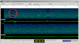
I also have downloaded, printed and studied the WSJT user guide. Here are some screen shots of my MS experience from this morning:


So the bit I have circled in the image above is the signals from DL5WP, you can clearly see a burst of received signals. Here is the other window in WSJT7 showing the decoding of those signals:


There's also a chat room for MS nutters here:

http://www.on4kst.org/chat/index.php

Where you can arrange QSOs and discuss MS stuff.

This morning I've worked DL5WP in Germany and S59A in Slovenia.

Thanks Chaps!

Over the Pond (Again)

Well,

I left my TS-590 running WSPR last night on Top Band, here are the results as a map:


So the crazy antenna that I made back here:

http://g0mgx.blogspot.co.uk/2012/08/top-band-what-happens-there-then.html

Is still working fine.

I'm wondering if I could convert the antenna for the even lower bands by changing the inductor - the answer is, of course, that I can. However, the efficiency of the antenna will be further reduced as the frequency decreases. I think I need to understand the maths behind the efficiency calculations before I do anything too hasty.

Here's the new Ham Cat helping out yesterday. I have a full week off work so have some plans for some insanity in the shack... watch this space.


Interesting, egh?

Thursday, 7 November 2013

Ouch - That's Noisy!

Well,

You may remember the radio I acquired a while ago, back here:

http://g0mgx.blogspot.co.uk/2013/10/another-one-really.html

And the trials and tribulations I have had over a suitable PSU for the PA in the radio. Well, eventually I have received a unit I bought from China. It's stuck in a box and looks like this:


Now, currently this SMPS is generating some horrendous noise from about 4MHz to about 6.5MHz (and probably in other places as well!). The noise is only audible on any of my radios with an antenna connected; nothing with the antenna connector pulled out.

There is a very bad example of the noise on the 60MHz CW frequency 5.373MHz, however if I stick the antenna into the Spectrum Analyser, I don't see anything different with the SMPS on or off, the trace is the same:


Odd, egh?

** UPDATE **

I conclude that the SA is nowhere near as sensitive as a HF receiver - hence the trace above doesn't show the QRM.

Anyhow, following some exchanges on the RSGBTech Yahoo Group, I've had some great advice from some SMPS wizzos and we ended up removing the earth from the SMPS board itselt (don't try this at home) and connecting the -ve power rail to the metal case and hence the mains earth.

Result? Problem solved - the noise has been eliminated.

The RX On the 1000MP is excellent, I've rearranged the shack to accommodate the radio a little:


The photo above was taken with the panoramic feature of my Nikon Coolpix - good egh?

Friday, 1 November 2013

The art of Calibration (Once More)

Well,

After playing some with frequency counters in software, I thought back to the frequency standard that I have from back here:

http://g0mgx.blogspot.co.uk/2011/07/ocxo-oh-you-mean-ocxo.html

I thought it worth a quick check that it's still (as near as damn it) on frequency. It's an oven controlled oscillator which means that the actual gubbins that creates the signal is inside a small metal box that heats up to a fixed temperature; thus eliminating temperature related drift.

There is a voltage adjust pin on the OCXO giving you +/- a few Hz. How well I can actually calibrate it remains to be seen, but for the purpose of this exercise being fairly close is good enough. When I made the original box I included a multi turn trimmer to alter the voltage on this pin and calibrated it against the radio I had here at the time - an FT950.

I have to assume that the Kenwood radio I got here:

http://g0mgx.blogspot.co.uk/2013/08/introducing-new.html

has been accurately aligned, it also contains a 1ppm (part per million) local oscillator - so it should be a good reference for me.

So, tuning the radio to my 10MHz reference signal with a grounded antenna connection I see this:


The spectrum analyser sees this:


Both pictures above are at the same Spectrum Analyser configuration, however the information on the screen differs. You can see the centre frequency in the top image and the bandwidth in the lower one. Each horizontal square is ten Hz, so it looks like I am very close according to this instrument.

I am going to make some kind of GPS disciplined frequency counter at some point, it might also be good to make a GPS disciplined voltage adjustment for the OCXO like this one:

http://ve2zaz.net/GPS_Std/GPS_Std.htm

I'm going to order the PCB for that project and see how I get on, I've also found what I think will be a suitable GPS receiver with a 1pps (pulse per second) output on eBay - that's winging it's way from China.

However, there's always the problem that a man with two watches never knows the correct time....

Interesting, huh?

Counting Once More

Well,

Back from A71 land for a week or two and I have been looking once again at the Signal Generator that I made back here:

http://g0mgx.blogspot.co.uk/2013/10/so-hows-sig-gen.html

I was wondering about my choice of frequency counter and wondered if I could do something better. You may recall the counter I made back here:

http://g0mgx.blogspot.co.uk/2011/07/pic-n-choose-how-to-count.html

This was a PIC based frequency counter that I have blown the dust off (well re-made actually), please excuse the paws in the picture:


So, that has a gate time (right now) of 1s and a very good resolution. I have calibrated it against my 10MHz shack frequency reference from back here:

http://g0mgx.blogspot.co.uk/2011/07/ocxo-oh-you-mean-ocxo.html

and it works very well. What I don't like about it is the fact that it's coded in assembly language - I would much prefer to come up with something using a high level language that utilises Arduino.

Now, the processors on the Arduino boards dont have the same kind of timers that the PICs have and they are synchronous (this means they are gated internally to the system clock) which results in a maximum frequency that can be counted of about 40% of the system clock speed. For all the boards I have that would be about 6MHz. Also the smaller boards like the Uno have a resonator clocking the processor rather than a crystal - making the timing very hit and miss. So, I wondered if I could do something a little smarter with Arduino. I am contemplating using an external clock (based on a cheap watch crystal) to drive an interrupt on the board to control timing and an external pre-scaler to increase the maximum frequency I can count to the tune of 1024. If I use a simple CMOS 4040 chip to divide the incoming frequency by 1024 (say), the tricky bit will be not limiting the counting to a 1024 resolution - I'm still pondering that one.

Here's the watch clock running at 32.768KHz (great software number egh? 32768 is 2 ^ 15):


If I were to use one of the on-board Arduino hardware timers I could divide this 32.768KHz by 256 and crate an interrupt routine that ran 128 times per second. That should give me enough control to be able to gate an external incoming frequency to exactly one second. If I can do that then we should have the basis of an Arduino frequency counter. Seems a bit complicated though!

If I am going to go to all that trouble to generate a 1 second counter gate, I wonder why I can't use an external GPS - they can generate spectacularly accurate 1pps signals based on the US DoD atomic clocks....

Here's the mess I am working with at the moment:


And here is new Ham cat asleep on the data sheets I am trying to use:


Damn crazy cat:


Bonkers, egh?