Search This Blog

Radio Guy Tees

Radio Guy Tees
Radio Guy T-Shirts

Saturday, 30 July 2011

OCXO? Oh, You mean OCXO.

Well

Following my previous deliberations over how to align a frequency counter, I ordered a 10MHz High Stability Crystal Oscillator from China via ebay. I have decided to use it to make a frequency reference for my shack.

All I have done is box the device with a suitable voltage regulator and a power switch & indicator:

So, as a bit of a sanity check, I tried zero beating the signal from this oscillator with my Yaesu rig:

that all looked pretty damn good to me.

So all that remained to be done was to calibrate the frequency counter:

What do you recon? Good egh?

Friday, 22 July 2011

PIC 'n' Choose how to Count

Well, I've been fiddling with some PICs today, most notably the 16F628A. I bought the chip and a nice LCD display on ebay quite some time ago with the intention of building a good quality bench frequency counter.

So, to cut a long story short, another project is born. I've thrown together an initial prototype, but as is normally the case, this has raised a few questions.

Firstly, how do I align the PIC clock to be exactly accurate? With a frequency counter perhaps? Recursion - see recursion.

Then once I've done that how do I calibrate the counter? Here I would need one of those oven baked OXO thingumabobs. There's quite a few of them on ebay but they all seem to be in China; not sure I want to wait for a delivery from China.


So threes the basic board; there isn't much to it except a small RF amplifier and the PSU for the electronics, oh and the PIC itself of course.

The first thing I realised when I started to do this was that my PIC Programmer was in fact obsolete! Can you believe it; it wouldn't program these new fangled chips, so I trundled to a new local Maplin store and came away with a PIC programmer in kit form:

That took just over an hour to build. It also includes some I/O circuitry and other bits and bobs so it should come in handy in the future. The serial protocol doesn't seem to be compatible with MPASM from Microchip; so I'm having to use a non IDE which is a pain.

The display that I bought simply ages ago looks really neat when its being used:
It is, however, close to impossible to take pictures of.

I have a feeling that this project is going to roll and roll...

The following pictures are here for two main reasons, firstly because I can, and secondly for my mum:

This is Chopsey cat asleep on my new suitcase:

 This is the Geddy cat asleep in my left arm:

And  this is Chopsey cat again, but this time he is stupidly chasing his tail (he does this lots):


Fun,. egh?

Sunday, 17 July 2011

It's running Hot Hot Hot!

I've been fiddling some more with my BITX:

http://g0mgx.blogspot.com/2011/01/boxing-bitx.html

and more specifically with the PSU that's built into it. I was using a 9-0-9 transformer, taking the 18V into the BITX. Once rectified and smoothed this was generating a basic DC supply of about 24V. Now, the 24V is a good value to feed directly to the IRF510 PA to get a good output, however, when I passed the 24V into the LM317 to regulate the value down to 12-13V the regulator was running really hot.

Thinking about the maths; then we have 24v in - 13v out = 11 * 0.8 (800mA) = 8.8 watts power dispassion! That's loads for a little LM317 to cope with even with the heatsync I've given it. I've been looking around for some time to try and find a suitable multi-voltage transformer such that I can have separate AC windings for the 13V regulated board supply and the PA. I found this on e-bay:


It was only the transformer I found on ebay, but I've built myself a power pack with a cabled 11.5V, +21V and 0V to the BITX. I'm about to drill the BITX case to take a 4-pin DIN socket and plug to act as the power pack DC connector so later today I'll be BITXing...


I'll keep you posted, but should be nice and cool!

Good egh?

Saturday, 16 July 2011

How Noisy is this?

Well, there have been a few developments here of recent; firstly the FT-920 has gone and been replaced by an ICOM IC-756 PRO II. The radio is currently sat permanently WSPRing on 6m.

But getting back to Homebrew, I have been trying to make a noise source for HF; the idea being that I can use this for testing filter bandwidth. I stumbled upon the following schematic which is from the RSGB publication Hombrew Cookbook - strangely my wife looked at the receipt and wondered why I wanted what she thought was a recipe book for making wine!

And this is my dead bug style build of the circuit:
The observant amongst you will spot that I have a reverse biased zener diode in there in place of the transistor that has been substituted for same in the schematic. I plan to try a few different diodes and transistor junctions to see what difference it makes. I'm certainly not seeing quite what I expected from this circuit. This is what the spectrum analyser makes of the circuit output (the large spike in the middle is 0 MHz):

 and if I move the 0MHz point left and increase the scan width to 2MHz per division:
So I wasn't expecting to see such a dramatic decrease in amplitude as the frequency increased. I cetainly wasn't expecting the spectrum analyser to show the inverse image from 0MHz and below!

So, I'm planning to try a few different zener diodes to see what the difference is; the theory is that there should be a good amount of white noise generated when a zener is reverse biased to the point where it reaches its reverse breakdown voltage.

Weird results, egh?

Wednesday, 22 June 2011

A most Diplexing Mystery

Well, finally a day when I can spend some time at play here in the shack; the next part of the project has to be the beginnings of the receiver front end. So, in true form, and trying to stay faithful to the articles in RadCom Homebrew, I've moved on to the 1st RF mixer and the diplexer that follows it. The basic concept of a diplexer is really a band pass filter. Post the RF mixer there will be a mix of the RF input (through a bandpass filter from an antenna) and the LO. My LO isn't yet built but I have a DDS VFO here which will do just nicely. My IF is already set at 9MHZ, but the RadCom articles are assuming an IF of 10.7 MHz so I have some maths to do.
There are loads of on-line references to diplexer design, but I found this to be a particularly good starting point:

http://www.qrp.pops.net/dip2.asp

and more specifically, this:

http://www.qrp.pops.net/dip_sup.asp


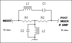
I'm wanting to build a Bridge-Tee RF Diplexer, a la:


and I now understand that I'm looking for a reactance for C1 and L1 of about 250R and for C2 and L2 a reactance of 10R at my chosen frequency of 9MHz.

Using my basic maths, and also this great on-line reactance calculator:

http://www.electronics2000.co.uk/calc/reactance-calculator.php

I've come up with values of C1 = 70.5pF, L1 = 4.42uH, C2 = 1760pF and L2 = 177nH.

When I wind coils I always tend to measure them out using my AADE LC meter:


So here I have wound 4.5uH when the theory suggested that 33 turns would give me 4.4uH, but it's close enough. I've built the diplexer here, and included some trimmers hopefully to peak the resonance:


And as per design, it peaks nicely at 9MHz. So post 1st RF mixer we should be able to bin all the other junk thats generated and have a clean (ish) signal. This is my homebrew signal generator:


Apart from suffering from the worlds brightest power light, it works very well. I stole the design from here:

http://www.phonestack.com/farhan/siggen.html

I'd like to add a second output at higher amplitude, but that's another project for another day.

As per normal, chief technical assistant has been close to useless today:


Fun, egh?

Monday, 20 June 2011

Not low enough?

I've been testing the Low Level Amplifiers from my last post. There is something very strange going on! The first amp, from the RadCom article, seems to have some pretty good gain:

The input signal is at 14.14 MHz and an amplitude of about 300mV, here the output is clearly looking OK and has an amplitude of about 17V pk-to-pk. That's a gain of 20 log (17/0.3) which is about 35dB - exactly on the nail with the design gain. However, as soon as I hook another scope probe on the input to compare the two signals, the circuit seems to oscillate and some of the gear in the shack goes a bit nuts. The signal generator display starts to ramp up and down frequency as does the voltage display on my bench PSU, I suspect there's just too much RF flying about. This is the ouput signal with no scope probe on the input:

and this is the display with both probes attached:
Looking at the second circuit, the one from here:

http://homepage.eircom.net/~ei9gq/transmit.html

The whole thing seems much more stable but I haven't got anything like the gain I expected. Also the transistors are running hot, hot, hot!

The output is only about 3V pk-to-pk which is only 20 log (3/0.3) - 20dB gain.

Here are the two circuits as they sit under test:

Confusing, egh?

Sunday, 19 June 2011

Low Level Amplifiers - how low can you go?

Well there's not been a great deal of progress within the shack recently, chief technical assistant is of little or no use most of the time, and he does insist on sitting on the most sensitive bits of RF engineering. That plus the fact that my job has been getting rather badly in the way of play time means I've made little or no progress recently.


I've been trying to make the Low Level Amplifier as part of my ongoing attempt to replicate the SSB transceiver being built in the Homebrew articles in RadCom. This is the schematic of the LLA, published in Feb 2011:
My build of the circuit is here:
Now, if anyone is actually paying any attention to this blog of mine, or anyone happens to come across this post, I'd be grateful for any comments on my construction pictured above. All I am finding with this LLA is that it oscillates at the slightest whim. I've started to blame my RF signal generator (yes that's homebrew also), and various other aspects including the capacitance in my x10 scope probes. But I've just decided to find an alternative. Now the author of the fantastic homebrew column also has a website, Ed - EI9GQ has an alternative circuit on his site here:

http://homepage.eircom.net/~ei9gq/transmit.html

So I've built that one also:

I'm planning to apply power to this tomorrow so will keep my blog updated with progress.

I keep trying!