Search This Blog

Radio Guy Tees

Radio Guy Tees
Radio Guy T-Shirts
Showing posts with label homebrew. Show all posts

Monday, 23 June 2014

Moving onwards and upwards....

Well,

Following on from my last post, I've been making some more bits and bobs to go with the SSB exciter:

http://g0mgx.blogspot.co.uk/2014/06/history-repeating.html

I've made the Triple Balanced Mixer:


As is becoming an apparent recurring theme, my isolation between the different ports isn't measuring as good as the author, however I can measure LO-RF and LO-IF isolation of about 40dB and more like 50dB of RF-IF isolation; which isn't at all bad.

The mixer uses 5 bifilar wound inductors, each of 12 turns on a FT37-43 and two well matched sets of diodes.

I have then added the post mixer amplifier and constructed the first of many band pass filters. This one is for 40M or 7.0 - 7.2 MHz.


Information on the filters is here:

http://homepage.tinet.ie/~ei9gq/bpf.html

which includes a link to a spreadsheet credited to John Charlton G3VRF which is an excellent calculator tool.

When I first built this filter is was too low in frequency (the yellow trace below) so I reduced the inductors by one turn each to get the purple trace. The markers are at 7.0MHz and 7.2MHz:


So the filter, at least, is now looking rather good.

I've had another good look at the exciter from last time but still I can't see why my output level is so much lower than the authors; will have to look again tomorrow!

Good, egh?

Sunday, 22 June 2014

History Repeating....

Well,

I've bought myself a new RSGB book; it's called "Building a Transciever" and is actually a reprint of a load of RadCom Homebrew columns. Those of you been here a while may remember I actually made the exciter from these articles a while ago back hare:

http://g0mgx.blogspot.co.uk/2010/11/radcom-dec-2010-ssb-exciter.html

Now, there has been a lot going on here since then and I probably have a bit more experience in these matters, so, to cut a long story short, I am planning to start again from scratch and have a go at the books contents.

The book itself is here:

http://www.rsgbshop.org/acatalog/Online_Catalogue_What_s_New_26.html

and the authors website is here:

http://homepage.tinet.ie/~ei9gq/

So, today I have made the exciter (again):


I could be a bit critical of this book (well actually I am and have told the RSGB so), here's why:


  • The photos in the book are exceptionally small (even compared to the original magazine copy)
  • They are black and white making component identification impossible in some cases
  • Some of the book schematics dont have all the component values in th picture or the text (crystal frequencies for the SSB exciter oscillator and also the Op-Amp in the Mic amp) - and that's just so far
Here's the output of my exciter on LSB with a 2KHz audio signal injected into the Mic amp and the carrier adjusted for what I think will be about right. Each of the SA images includes a sweep of the crystal filter - I have no real idea why the top of the passband has appeared to be so wibbly wobbly - could it be an impedance thing? The filter is 450 ohm ish and the SA is 50 - but I doubt it somehow.


I've used a GQRP club SSB filter 10.7MHz and the two carrier crystals that match it; however, my USB carrier point was **way** too high in frequency so I have had to add an inductor into the circuit to pull the crystal downwards (this is why I would like to know what frequency crystals the author used). Here's the exciter in USB:


Also the output of my oscillator is no where near the amplitude the author suggests he had from his. We will see.

Here's another shot showing the actual frequencies of my USB and LSB carriers:


I used a TL072 op-amp in the mic amp and here are the gain figures I measured:


So, all in all a good start I think.

Here's the latest two additions to the household (the dogs not the wife - she has been around for quite a while):


Good, egh?

Sunday, 15 December 2013

Testing Times for my Linear Project!

Well,

You may recall the 50/70MHz linear that I last reported on back here:

http://g0mgx.blogspot.co.uk/2013/12/70mhz-linear-progress-is-steady.html

The first thing I need to do is to test the main amplifier block to confirm all working as planned. Now, to do this I need a fairly accurate 70MHz signal to amplify - the problem is that the signal generator I made back here:

http://g0mgx.blogspot.co.uk/2013/10/so-hows-sig-gen.html

doesn't go that high.

Some of you may recall when I first started meddling with 70MHz that I made an experimental 70MHz transmit converter to take a 10MHz signal and mix it up to 70MHz back here:

http://g0mgx.blogspot.co.uk/2012/07/mixing-better-than-before-70mhz.html

So I have dug that board out again, dusted it off and straightened a few bits that had got bent in the draw and stuck some power on it. I have the signal generator at 10MHz connected to the RF in port:


So in the picture above we have a 60MHz local oscillator and associated amp and filter along the top of the board, the connector on the RHS has the 10MHz signal from the signal generator then there is a diode doubly balanced mixer feeding another amp and output filter along the bottom. The output of this looks like this on the Spectrum Analyser:


And here on the 'scope:


It's important to understand that the Spectrum Analyser is a 50 ohm instrument - the 'scope isn't - hence the 'scope is terminated in a 50 ohm feed through you can see in the picture below:


So, using the data from the 'scope (which I suspect isn't too accurate at 70MHz) we can do some maths to calculate the power out of this concoction:


So, using the peak-to-peak voltage reading from the 'scope I get a power reading of about 1dBm. So, let's now connect the signal to the accurate power meter I built back here:

http://g0mgx.blogspot.co.uk/2012/11/the-art-of-calibration.html

And this is what I see (apart from a stupidly bright power light):


and if I set the reference level on the Spectrum Analyser to 10dBm this is what the signal looks like:


So it looks very much like a 0dBm signal at 70MHz to me.

All this test gear is really coming together- I trust the dBm meter I made very much - a great deal of effort went into calibrating it and there is no reason it should deviate from it's set up.

So now I need to hook up some power to the amplifier brick, terminate it through a power meter to a dummy load, throw the switch and see what happens.... watch this space.

Good, egh?

Monday, 2 December 2013

Low Pass - Looks More Wobbly to me!

Well,

You may recall the basic ideas for a 4 and 6M linear that I discussed back here:

http://g0mgx.blogspot.co.uk/2013/11/now-that-smoke-has-settled.html

I've started to fiddle with the software and have most of the basics working. The software will just about control everything in the amplifier including cooling and alarms. The most important alarm will be the over drive - I suspect even with input attenuation I am going to find it very easy to overdrive the amp.

I started a few days ago to make the low pass filter. My first attempt looked kind of OK and used air cored inductors, but when I hooked it up to the spectrum analyser and tracking generator I didn't like what I saw at all:


The overall response wasn't very flat and at the target frequency I had quite a bit of attenuation. As a consequence and thinking it was my inductors that were suspect I ordered some T50-10 torroids as these would be good at 70MHz and also would create the required inductances with a reasonable number of turns.

The Low Pass Filter design has evolved a little bit and now looks like this in theory:


So after the T50-10s duly arrived a re-wound all the inductors only to find exactly the same result. Hmmm.

So, then I tried:

  • Winding Air Cores with a smaller inside diameter
  • Reducing the capacitor values and adding trimmers so I could fiddle with the filter
  • Going for a curry
None of the above helped much, the results were still rather rubbish at my target frequency i.e. I had buckets of attenuation where I didn't want any.

Then I tried using some different test leads:


Conclusion? The test leads I was using are spectacularly rubbish at 70MHz - Aaarrrghhhh!!!!

I do have a slight bit of attenuation at my target frequency - the slope is starting just a little too soon, and I need to decrease the capacitors either side of the center inductor a tad.

So here's the filter as built right now:


So I can only conclude that the first attempt at the filter was fine, I just didn't know! The moral of this story is to always connect the test leads from the Tracking Generator output to the Spectrum Analyser input without the circuit under test in the way to ensure you have a flat line - do this first!

Here's the ham cat:


Annoying, egh?

Sunday, 1 December 2013

80M into 43 feet - That doesn't go!

Well,

I've been looking around for some time for some means of getting a signal onto 80M. I thought about creating something like the inductive antenna I made for top band back here:

http://g0mgx.blogspot.co.uk/2012/08/top-band-what-happens-there-then.html

But I found this link the other day, and this looked like it was worth a go:

http://www.sral.fi/turva/G7FEKantenna.pdf

The antenna looks like this:

So we have both sides of the open wire feeder connected to the centre of the coax feed and the antenna itself fed against ground.

I've taken down the 10MHz dipole I had up in the air and made one of these and put it in it's place. The open wire feeder comes down rather close to the house but it's all fitted OK:


On the earth or counterpoise side I have attached 60' of copper wire which ambles it's way along the ground down the garden and then across the bottom of the plot. I've also dug out a set of cut counterpoise wires I made to take to Malta with me and attached them and strung them out in the flower beds also.

I've just been listening to a DK5 caling CQ and he is an S3 on the windom I have from here:

http://g0mgx.blogspot.co.uk/2013/08/so-who-is-caroline-ah-carolina-windom.html

and S9 on this new antenna.

Only time will tell, but initial signs are promising.

This cant be a comfortable place to sleep, can it?


Fun though, egh?

Saturday, 16 November 2013

GPS Disciplined - Really?

Well,

After a great deal of fiddling, learning, scratching my head then fiddling some more, I have finished my GPS disciplined Frequency Standard:


This is a project by VE2ZAZ:

http://ve2zaz.net/GPS_Std/GPS_Std.htm

So, what's this all about then?

Basically we have an oven controlled crystal oscillator (OCXO) which can be fine tuned by applying a voltage to an adjustment pin. Typically this adjustment is only +/- a few Hz around the target frequency anyhow. The oscillator itself is the large metal box you can see in the image above - it has a sticker on it saying "Used". This box is actually the oven - and yes - it heats up to maintain the crystal inside at a steady temperature.

So, we have a PIC processor on the green PCB you can see and this basically monitors the output of the OCXO and compares that to a 1pps signal from the GPS receiver. Having a known 1pps signal means we can determine if the voltage on the OCXO needs to be increased, decreased or left as-is.

That's the bottom line of the whole thing.

Now, the firmware (read software) does some stuff with averages and a state machine to determine if the output is within certain accuracy parameters, but basically it's keeping the OCXO on track.

How accurate can this be?

Well, I have mine configured to make an adjustment every 20 Hex or 32 samples. Each sample is fixed at 16 seconds (expecting 16 million counts from the OCXO).

So my averaging period is 16 * 32 = 512 seconds (or about 8.5 minutes).

Therefore the best possible accuracy I can expect is 1 in (10MHz * 512s) = 2.0E-10 (ish)

So, it's more than adequate enough for my purposes. I need to leave this running for a while and monitor the output - there's a serial connection to a "dumb terminal" spitting out data as the unit trundles away to itself.

The output waveform looks like this, this is the 10MHz signal:


There's also another output switchable between 5 MHz and 1 MHz.

Initially I had problems with the 1pps signal not seeming to be at 1pps! The symptom was that the count recorded by the unit after each 16 second sampling period would suddenly be wildly out and every 1 in 4 would seem to be accurate. Will some great assistance via email, eventually this was found to be due to noise on the PSU lines to the main PCB. I've ended up adding some extra smoothing to the +8V line that feeds the main board and the OCXO driving op-amps. This plus some extra capacitance where the lines physically connect to the board seems to have solved the problem. I also ended up adding a simple RC low pass filter to the 1pps line where that enters the microprocessor, but I don't think that had any effect at all.


I've used the output from this to calibrate the counter I made recently:


This is Geddy Cat, he is by far the best cat in the world:


Good, egh?

Wednesday, 13 November 2013

Frequency Reference - How Accurate?

Well,

You may remember I mentioned a GPS disciplined Frequency Reference project that I found back here:

http://g0mgx.blogspot.co.uk/2013/11/the-art-of-calibration-once-more.html

I ordered and received the PCB for the project, here's the start of construction:


The main PCB connects to a OCXO which it alters the control voltage to adjust, and also connects to a GPS receiver.


Now, I started off with a GPS receiver that was advertised as being a timing and 1pps (pulse per second) output device. This is exactly what I need as the 1pps signal from the GPS timing is used to gate the counting of the signal from the OCXO and hence alter the frequency to be exact.

Anyhow, the GPS I bought, despite what it was advertised as being, didn't contain the 1pps firmware!


So I have another unit now, this one certainly does contain the 1pps gubbins, but I don't have the correct connector for the antenna feed! However, here's what the 1pps signal looks like:


As this is only about 3V +ve I suspect I will need to push this through a transistor switch, but whatever happens it looks good to me!

I've got 2 10MHz OCXOs here, and you can see them below on test:


The physically larger unit to the rear of the photo above has a variable adjustment between 0 and 8V, the one near the front is 0 - 2.54V. Also the one at the front seems to pull a huge amount of current while it is warming up its oven - like 2A.  That is going to present some difficulties; the rear unit only pulls about 500mA. So I'll probably go with the 8V adjust unit initially and see how it performs.

Cat's not impressed:


Fun though. egh?

Monday, 30 September 2013

So, What's happened to the bridge then?

Well,

You may recall my musings from my build of a Return Loss Bridge back here:

http://g0mgx.blogspot.co.uk/2013/09/where-does-it-lead-bridge-to-nowhere.html

And I was rather disappointed with the directivity I was achieving when measured using my dummy load and digital 'scope.

Well, I've got myself a Huber-Suhner low power dummy load (I am told they are quite good quality) and have attached this to the RLB using a Female N-Type to PL259 then a SO-239 to BNC adaptors stacked together. Anyhow, I have measured the RLB from my previous post again and am getting these results now:


And that is certainly much better, now, I tried to make a new RLB today using a different balun arrangement as I described here:

http://g0mgx.blogspot.co.uk/2013/09/time-time-time.html

and it looks like this in a die-cast box (it's a complete mess thanks to my metalwork capabilities):


In the photo above you can see the Huber-Suhner load and also there is a 50R terminator visible in the bottom of the picture. Rather than having a "known" 50R inside the RLB, this one has a fourth socket so you can attach the "known" impedance - meaning that you could use this device at impedances other than 50R.


If you look closely above you can see that this is more of a plumbing job than soldering.

Now, I nearly put this straight in the bin when I got it all wonky in the box and generally made a mess of the whole thing, but then I thought I would just see how it worked. Here's the directivity I am measuring:


So, this looks quite good - I think...

Confusing egh?

Sunday, 29 September 2013

Time, Time, Time

Well

I've been busy, busy, busy with work - spent two weeks trundling around Qatar and the United Arab Emirates and then a full week in Sri Lanka. Got off the Aeroplane in Manchester and headed straight for the National Hamfest where I spent two days in my official capacity as "RSGB Guy".

Finally I am home.

This weekend was the CQ WW RTTY Contest; which means it is a year since I got my linear:

http://g0mgx.blogspot.co.uk/2012/09/how-much-power.html

Last year I spent quite a bit of time playing in the contest, this year sadly only a few hours. Here, however, is my log converted to map format:


So despite the lack of time, there are a few good contacts in there.

Before I went away I ordered a step attenuator kit from QRP Kits:

http://www.qrpkits.com/

I have to say that the stuff I have ordered from them in the past has been first class; this is no exception. The metalwork for this project is particularly excellent quality:


So that's built and will be a very handy addition to the shack.

You may also recall my musings with Return Loss Bridges back here:

http://g0mgx.blogspot.co.uk/2013/09/return-loss-bridge-where-does-it-lead.html

And you may also recall that I sometimes bounce ideas off Kerry, VK2TIL (who is perhaps the worlds greatest homebrewer). So some correspondence with Kerry has resulted in some ideas to improve directivity by using a different type of balun and construction method. I am aiming to replicate something like this:


So at the HamFest I found some suitable binocular cores and have made this:


So, I now need to couple this up to some BNC connectors and take some measurements.

I have a full week off before returning to A71 land; my plan is for real time, fun time and perhaps sausage time.

Fun, egh?

Friday, 6 September 2013

Bench Sig Gen - Any bright ideas?

Well,

Been fiddling around at home today and building a bench RF Signal Generator. I have a homebrew one already but it's a bit hit and miss to tune, I also have an old Avo valve based signal generator, but that's extremely heavy, very large and generates lots of heat!

I saw a schematic for a suitable bench Signal Generator a while ago in Experimental Methods in RF Design (page 7.15 Fig 7.27), so I thought I would have a go at making one.

Here's what it looks like in it's current state of construction:


The tuning capacitor on the RHS is the main tuning and the second variable capacitor on the LHS is the fine tuning; that should help make it easier to set the device.


The toroid you can see nearest the front of the picture above is a little odd; the secondary is just a single turn which in reality is the leg of the diode you can see just passing through the centre.

I then found in my box labeled "projects" a digital dial kit from QRP kits:

http://www.qrpkits.com/freqcounter.html

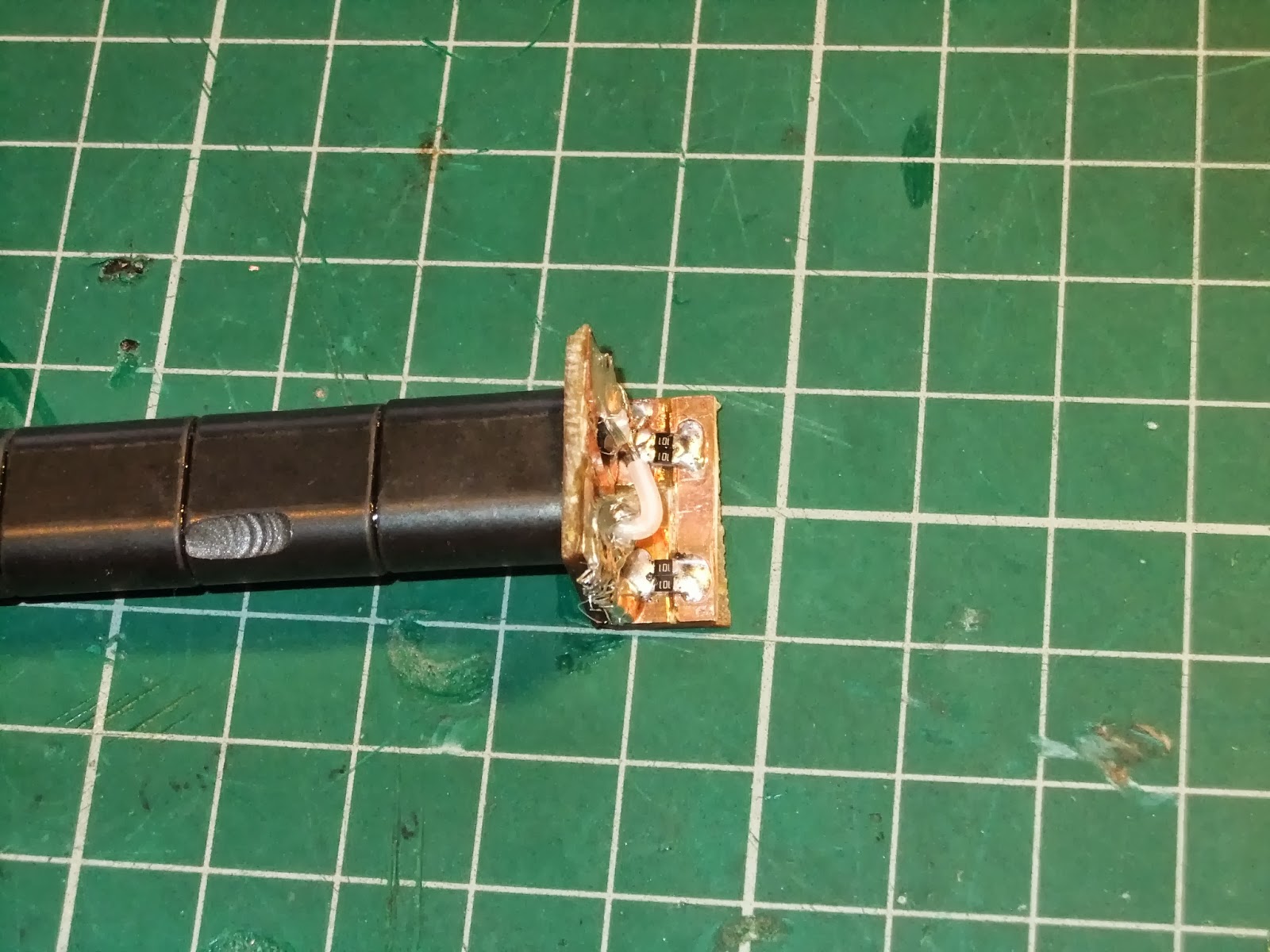
I've used these in projects in the past and I must have ordered an extra one some time ago, anyhow as this is a surface mount project, it was extreme soldering time again. If anyone doesn't realise how small these components are, here's one of the resistors on my thumb nail:


So, here is the underside of the project board completed:


And the display side:


Ideally you would calibrate this with as high a frequency as possible, but I have used my 10MHz frequency standard from here:

http://g0mgx.blogspot.co.uk/2011/07/ocxo-oh-you-mean-ocxo.html

And here is the counter connected to the signal generator, I've added an additional buffer output stage between the output PAD and the counter in my build:


So, the output of the new bench Signal Generator looks quite good, here's some shots of the device set at 10MHz exactly:


This now needs a case, but I am going to wait until the end of the month when I will be at the National Hamfest and see if I can find anything there. I'm away between now and then in A71 land so it will just have to wait.

There is an expression about curiosity and cats:


Good though, egh?