Search This Blog

Radio Guy Tees

Radio Guy Tees
Radio Guy T-Shirts

Monday 30 September 2013

So, What's happened to the bridge then?

Well,

You may recall my musings from my build of a Return Loss Bridge back here:

http://g0mgx.blogspot.co.uk/2013/09/where-does-it-lead-bridge-to-nowhere.html

And I was rather disappointed with the directivity I was achieving when measured using my dummy load and digital 'scope.

Well, I've got myself a Huber-Suhner low power dummy load (I am told they are quite good quality) and have attached this to the RLB using a Female N-Type to PL259 then a SO-239 to BNC adaptors stacked together. Anyhow, I have measured the RLB from my previous post again and am getting these results now:


And that is certainly much better, now, I tried to make a new RLB today using a different balun arrangement as I described here:

http://g0mgx.blogspot.co.uk/2013/09/time-time-time.html

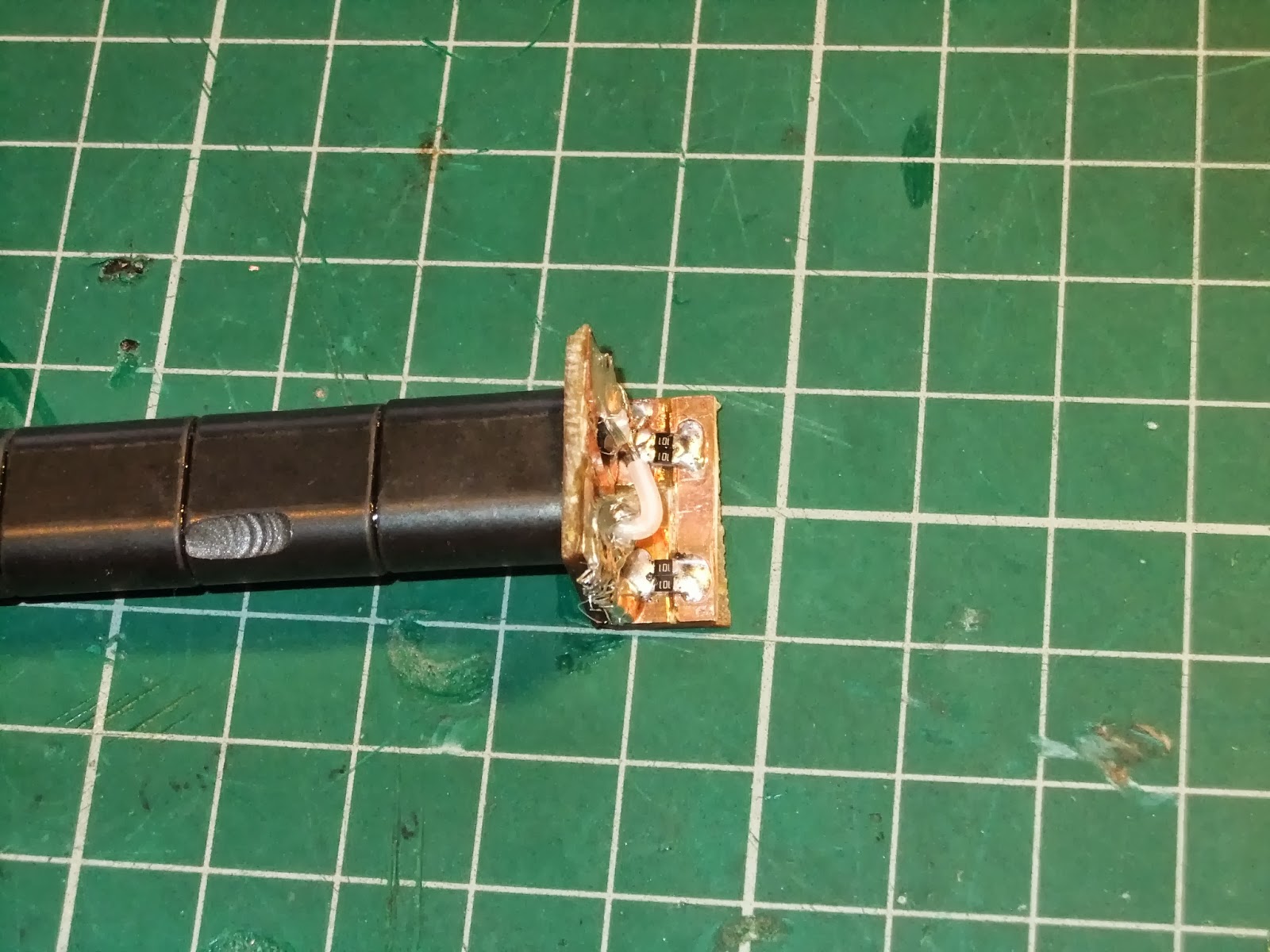
and it looks like this in a die-cast box (it's a complete mess thanks to my metalwork capabilities):


In the photo above you can see the Huber-Suhner load and also there is a 50R terminator visible in the bottom of the picture. Rather than having a "known" 50R inside the RLB, this one has a fourth socket so you can attach the "known" impedance - meaning that you could use this device at impedances other than 50R.


If you look closely above you can see that this is more of a plumbing job than soldering.

Now, I nearly put this straight in the bin when I got it all wonky in the box and generally made a mess of the whole thing, but then I thought I would just see how it worked. Here's the directivity I am measuring:


So, this looks quite good - I think...

Confusing egh?

Sunday 29 September 2013

Time, Time, Time

Well

I've been busy, busy, busy with work - spent two weeks trundling around Qatar and the United Arab Emirates and then a full week in Sri Lanka. Got off the Aeroplane in Manchester and headed straight for the National Hamfest where I spent two days in my official capacity as "RSGB Guy".

Finally I am home.

This weekend was the CQ WW RTTY Contest; which means it is a year since I got my linear:

http://g0mgx.blogspot.co.uk/2012/09/how-much-power.html

Last year I spent quite a bit of time playing in the contest, this year sadly only a few hours. Here, however, is my log converted to map format:


So despite the lack of time, there are a few good contacts in there.

Before I went away I ordered a step attenuator kit from QRP Kits:

http://www.qrpkits.com/

I have to say that the stuff I have ordered from them in the past has been first class; this is no exception. The metalwork for this project is particularly excellent quality:


So that's built and will be a very handy addition to the shack.

You may also recall my musings with Return Loss Bridges back here:

http://g0mgx.blogspot.co.uk/2013/09/return-loss-bridge-where-does-it-lead.html

And you may also recall that I sometimes bounce ideas off Kerry, VK2TIL (who is perhaps the worlds greatest homebrewer). So some correspondence with Kerry has resulted in some ideas to improve directivity by using a different type of balun and construction method. I am aiming to replicate something like this:


So at the HamFest I found some suitable binocular cores and have made this:


So, I now need to couple this up to some BNC connectors and take some measurements.

I have a full week off before returning to A71 land; my plan is for real time, fun time and perhaps sausage time.

Fun, egh?

Friday 6 September 2013

Bench Sig Gen - Any bright ideas?

Well,

Been fiddling around at home today and building a bench RF Signal Generator. I have a homebrew one already but it's a bit hit and miss to tune, I also have an old Avo valve based signal generator, but that's extremely heavy, very large and generates lots of heat!

I saw a schematic for a suitable bench Signal Generator a while ago in Experimental Methods in RF Design (page 7.15 Fig 7.27), so I thought I would have a go at making one.

Here's what it looks like in it's current state of construction:


The tuning capacitor on the RHS is the main tuning and the second variable capacitor on the LHS is the fine tuning; that should help make it easier to set the device.


The toroid you can see nearest the front of the picture above is a little odd; the secondary is just a single turn which in reality is the leg of the diode you can see just passing through the centre.

I then found in my box labeled "projects" a digital dial kit from QRP kits:

http://www.qrpkits.com/freqcounter.html

I've used these in projects in the past and I must have ordered an extra one some time ago, anyhow as this is a surface mount project, it was extreme soldering time again. If anyone doesn't realise how small these components are, here's one of the resistors on my thumb nail:


So, here is the underside of the project board completed:


And the display side:


Ideally you would calibrate this with as high a frequency as possible, but I have used my 10MHz frequency standard from here:

http://g0mgx.blogspot.co.uk/2011/07/ocxo-oh-you-mean-ocxo.html

And here is the counter connected to the signal generator, I've added an additional buffer output stage between the output PAD and the counter in my build:


So, the output of the new bench Signal Generator looks quite good, here's some shots of the device set at 10MHz exactly:


This now needs a case, but I am going to wait until the end of the month when I will be at the National Hamfest and see if I can find anything there. I'm away between now and then in A71 land so it will just have to wait.

There is an expression about curiosity and cats:


Good though, egh?

Thursday 5 September 2013

So what can you do with this bridge?

Well,

Now I've got what I think is a reasonable Return Loss Bridge - what can I do with it?

Lets take a very simple example, we have already noted previously that you calculate the Return Loss by:

where:

Open = Peak to Peak voltage with no connection to the "?" port
DUT = Peak to Peak voltage with the Device Under Test connected to the "?" port

So if we were measuring the output with an oscilloscope we would use that equation to calculate the difference in dBm. However, as I have a Spectrum Analyser that reads directly in dBm, in this example I'll cut some corners.

So, initially I have the Spectrum Analyser and the RLB set up like this:

To start with I have the "?" Open and my Spectrum Analyser, at my selected test frequency of 7.1 MHz sees this:


So at 7.1 MHz we have a signal from the Tracking Generator of -31.67dBm. Now, lets couple up the Carolina Windom I made here:

http://g0mgx.blogspot.co.uk/2013/08/so-who-is-caroline-ah-carolina-windom.html

to the "?" port. Now the Spectrum Analyser can see this:


So now, at 7.1 MHz we have a signal strength of -42.74 dBm - that's a difference of 11.07 dBm.

If we now use this equation to calculate the VSWR:

and plugging in the results:

we can calculate that the VSWR is 1.78.

Now, what does my newfangled Antenna Analyser thingamabob think the VSWR is at 7.1 MHz


the RLB works, doesn't it?

Wednesday 4 September 2013

Where does it lead? A bridge to nowhere!

Well,

Following my initial attempts at making a Return Loss Bridge (RLB) last time:

http://g0mgx.blogspot.co.uk/2013/09/return-loss-bridge-where-does-it-lead.html

I've taken some advice; the most common suggestion was that my construction was too slap dash! Could do better and must try harder - reminds me of my school reports!

Here's a remade version of the RLB in quite high-res:


Now this is much neater, however, the basic problem is going to be (so I'm being told) that the wires and the box create a feedline - my construction makes that feedline a load of pants....

Now, I then tried to make an alternative RLB using more normal type of construction techniques:


And that has a slightly worse directivity reading to the one in the box!

So, then I followed another suggestion and constructed an RLB using SMD resistors and this one looks like this:


The observant amongst you will see that the resistors are in fact 52R3 (thats 52 point 3 ohms); these were left over from the power meter project back here:

http://g0mgx.blogspot.co.uk/2012/11/the-power-is-with-me.html

This newly made RLB when boxed measures at 26.3 dB directivity - so this is an improvement and much closer to my target value of 30 dB.


I then decided to rummage further and I found some 100R SMD resistors, and made a third (forth?) RLB using 2 100R resistors in parallel for each 50R theoretical component:


Now this version of the RLB measures as 23dB directivity - so just the same as the first one! Bah - I'll stick with the version containing the 52R3 components for now....

New ham cat's not been helping much:


Fun, egh?

Return Loss Bridge - Where does it lead?

Well,

More fiddling today and I have been making a return loss bridge to help with my "RF Workbench" measurements.

A RLB (Return Loss Bridge) is a device that will help me understand how close to a desired target impedance of 50R things are. And by things I mean kind of anything really, an amplifier, a dummy load, an antenna, a rubber plant - anything. That last item isn't necessarily true - I am just checking you are paying attention.

What a RLB does is allow you to measure the difference between the input power and the power reflected as a result of an impedance miss-match. So the higher the return loss the better the impedance match (unlike SWR where lower numbers indicate a better match).

Here's a simple schematic of an RLB that I have stolen:


So, I've made mine using 2 x 100R resistors in parallel for each of R1, R2 and R3 and the transformer T is wound with 10 turns bifilar on a FT37-43:


Now, to calculate the bridge directivity, firstly you would connect a 50R output signal generator at the test frequency to the "RF" port and a 50R terminated 'scope at the "Detector" port. Once this is set up we need to measure the peak-to-peak voltage reading on the 'scope. In my case I set this up for 7MHz and read a value of 57 mV with the "?" port open circuit. If I now connect a 50R load to the "?" port and take the reading again, I get a value of 3.7 mV. This tells me that the directivity of the bridge is:

20 LOG (57 / 3.7) = 23 dB (ish)

Now, that's a bit pants! I was hoping for at least 30dB. THe first thing I tried was changing the toroid in the transformer "T" - I remade it using a FT37-50 with 10 bifilar turns:


This change hasn't made any difference at all!

The theory of operation is that you would set your signal generator to the frequency required and then first measure the detector reading with the "?" port open and then repeat the measurement with the device under test connected to the "?" port like this:

But given that my RLB only has a directivity of 23 dB ish I think I need to make some improvements. This should turn out to be a useful addition to the shack however, and in my quest to learn more and more about RF measurement, impedance and the like - this has been a good experiment!

Odd, Egh?

Tuesday 3 September 2013

A Pixie - Really?

Well,

Been fiddling recently with some very basic CW transceiver designs, most notably the classic QRP "Pixie" design.

This is a very basic CW transceiver comprising a Colpitts oscillator, a second stage which is an RF Amp in TX and a mixer in RX plus an Audio Amp. The basic schematic looks something like this:

I stole the image above from The free information Society:

http://www.freeinfosociety.com/electronics/schemview.php?id=1943

I've substituted the MPSH10 transistor in mine, but apart from that it's going to be the same circuit except for a different band.

To build one of these for a different band, it should be a case of changing the crystal frequency and also the output filter.I'd like to make one of these for the CW end of 20M; this led me to do some investigation into Low Pass output filters. Starting in the most excellent reference book Experimental Methods in RF Design, we can design a very simple Low Pass Filter like this:


Having constructed the filter above, it was clear that the roll off wasn't very sharp, so I did the maths for a 5 pole filter (above is a 3 pole). Here's the 5 poll filter constructed in a very experimental way:


I've hooked one side of the filter up to the Tracking Generator in the Spectrum Analyser and the other to the Analyser input, here's what I see:


Which means that when the basic oscillator in the Pixie is connected to this filter as its output low pass, we get this suppression of the output harmonics:


Which all looks rather good to me!

As an alternative to the "norm", here's a picture of Saki dog:


Fun, egh?