Search This Blog

Radio Guy Tees

Radio Guy Tees
Radio Guy T-Shirts

Sunday 18 October 2020

Balun Output Impedance

 Well,

Lots of discussions about my baluns and the test setup, a common question seems to be how to measure the output impedance.

Here's my way:


Fun, dont you think?

Wednesday 14 October 2020

Progress is slow and steady

 My little YouTube channel continues to progress slowly:


Good fun!

Its Funny What you can Find

 Well,

Can anyone offer a translation?

Thanks for the credit in the description :-)

Wednesday 9 September 2020

Baluns, Baluns, Baluns!

 How about this for a bit of bonkersness?


Fun, dont you think?

Thursday 6 August 2020

The new Icom IC-705

With much thanks to the boys at LAM Communications in Barnsley I got my paws on a pre-production release of the new Icom IC-705. Here's my brief introduction to the RX capabilities of this tiny new rig:


It's amazing!

Tuesday 30 June 2020

Why can't Icom do this?

Well,

I've been critical of my IC-7610 and the lack of audio spectrum display centred around the CW pitch frequency - the Kenwood 890 has it.

I recently came accross a design in Practical Electronics for a simple audio spectrum analyser and decided to build one as an experiment. The DSP chip cost less than 3 GBP.

I wonder why Icom can't do this?


Monday 29 June 2020

The CAT Macro

Well,

I've had a few folk contact me directly recently asking about rig control using macros and CAT commands.

I did a quick video to demonstrate the concept with Logger32 and then Ham Radio Deluxe:


I hope this is useful to someone!

If you like what I am doing on YouTube, please subscribe to the channel, I would very much appreciate your support.

CAT control at its best:


Saturday 27 June 2020

The old and the new

Well,

Whilst rummaging in the attic looking for something, I stumbled accross this old Direct Conversion receiver I built when I was a young whipper snapper. This is a design by Drew Diamond, VK3XU and is published a the G-QRP club book called "Radio projects Vol 1".

I did a video for my YouTube channel having a look back at my construction capabilities from all those years ago:


I hope you enjoy!

Monday 22 June 2020

Funny old World

Well,

I've been having an e-mail exchange with a Radio Amateur in New Zealand - he has been trying to get one of my YouTube projects based on the STM32 blue pill boards to work.

Following a few emails back and forth, he sent me this:


which is nice :-)

My latest ramblings on YouTube are all about the classic Sudden HF receiver, you should check it out!


Fun, don't you think?

Sunday 31 May 2020

CQ WW WPX - CW Contest Time

Well,

I've been having a play over the weekend in the CQ WW WPX CW Contest. Here's the log as a map:


There was interesting "blanketing E" propagation, but no real DX.

I did a quick video on the TS-890 in these busy contest conditions with Writelog, CW Skimmer and CW Get:


Fun, egh?

Friday 15 May 2020

IC7610 In Action!


Well,

By popular request I have put together a demonstration of the IC-7610 in action:


I hope you like it!

Sunday 10 May 2020

An experimental STM32 Frequency Counter

Well,

In an attempt to learn more about microcontroller programming I have done a little bit of training during this Covid-19 lockdown:


My first real attempt to use these skills is below. I've used a GPS 1pps signal to accurately count an external frequency. This is a GPS disciplined freuqnecy counter:


Good, isn't it?

Here is a picture of me (with Covid-19 dog clipper hair cut) and my beloved Bonnie dog:


Saturday 9 May 2020

A Modest Milestone

A nice little milestone today, if you'r not already subscribed to my YouTube channel I would very much appreciate your support:

http://www.youtube.com/c/MarkG0MGX


Local conditions.

Thursday 30 April 2020

GPS Disciplined, again?

Well,

I've been trying to learn more about STM32 microcontrollers, their programming and to understand more about the on-board peripherals.

This is the result of my musings:


Fun, egh?

Sunday 19 April 2020

TS-890 (Again) - Digital Config

Well,

By popular request I have created my best shot at an "idiots guide" to setting up digital modes on the TS-890:


I hope this is useful to someone....

Saturday 18 April 2020

A CW & WSPR Beacon

Well,

I've been fiddling some more with STM32 and have created a DDS based CW & WSPR beacon for 6M.

You can find the details of the project here:


The WSPR code is stolen from Anthony F4GOH, his code and other bits and bobs are on GitHub here:

https://github.com/f4goh/wspr

To counter any drift in the DDS, I've modified my AD9850 board to use an external signal for the clock and configured my Leo Bodnar GPS referenced oscilator to give me 10MHz from output 1 and 125MHz from output 2, thus:


The 125MHz is now used to drive the DDS. I'd be delighted to receive reports from the beacon, the CW signal is on 50.030 and every multiple of 10 mins it sends a 2 min WSPR transmission on 50.293 + 30Hz.

Here's the WSPR beacon RX from G0ORC:


No drift - not even a wobble! Excellent.

Fun, dont you think?

Wednesday 25 March 2020

An Arduino based Power Meter

Well,

I've been fiddling some more since the Linear we built a little while ago here.

Some musings below on power meters, directional couplers and measuing RF power:


I hope you are all keeping safe - its very scary out there.

Wednesday 11 March 2020

TFTs and Blue Pills - Are you sure?

Well,

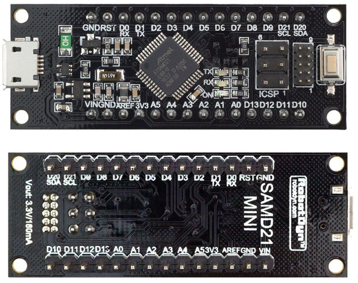
I've been using the STM32 processor (STM32F103 for those playing along at home) based "Blue Pill" board. This board is compatible with the Arduino IDE and I have been using it with the ILI9341 super duper TFT display module.

This is the board in question:


The STM32 board support can be added easily to the Arduino IDE, just add this line:

https://github.com/stm32duino/BoardManagerFiles/raw/master/STM32/package_stm_index.json

to the preferences screen:


Once you have done that you can then install the STM32 cores from the board manager:


I wrote some very simple code to generate Pi using floating point maths:


Set to calculate 100,000 itterations, the good old Arduino Nano ran this code in 29.60099983215332031250 seconds. This Blue Pill board runs the same calculation in 3.07200002670288085937 seconds. Cooking!

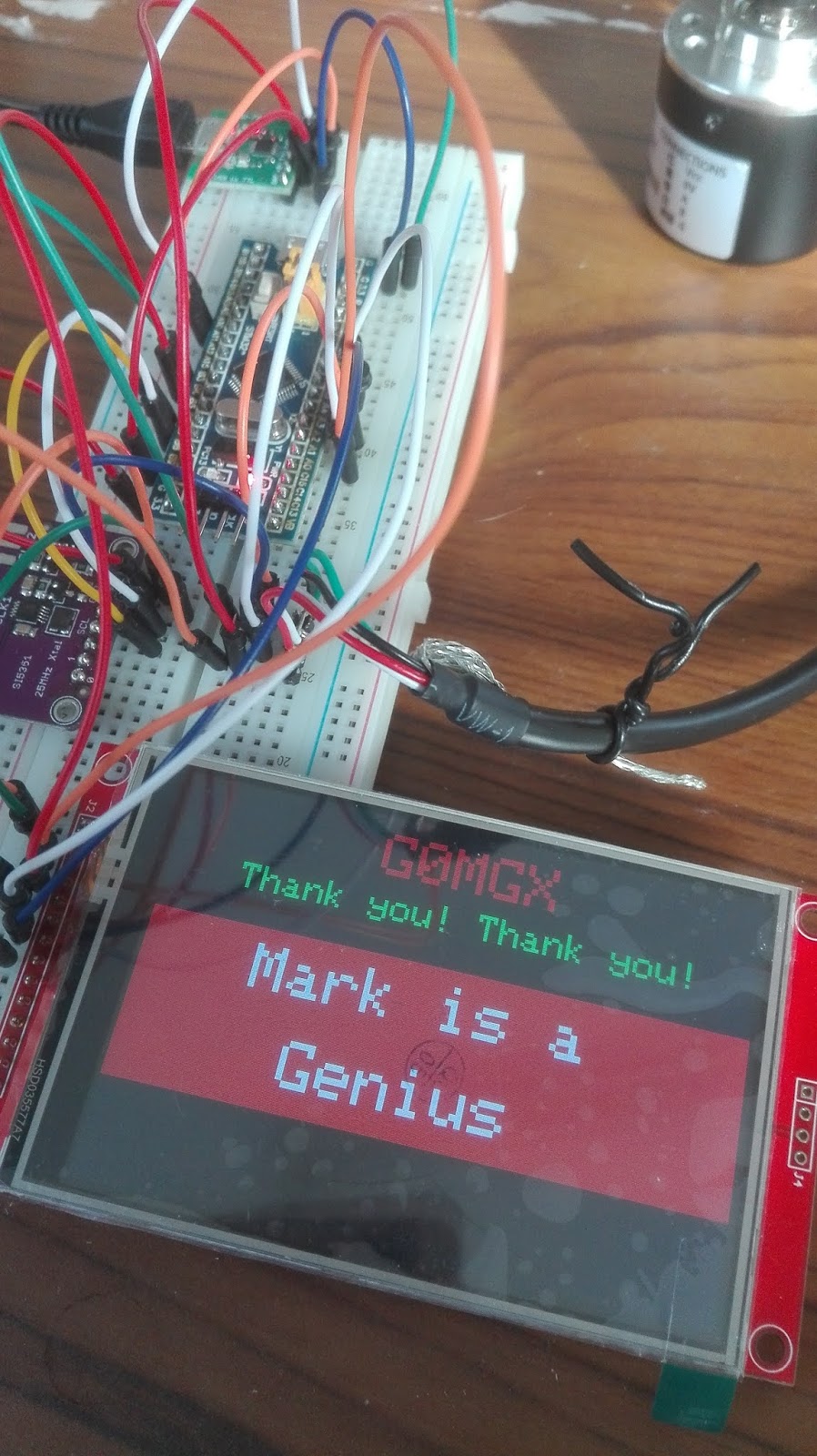
Here' how I have wired the test up for the TFT:


I have used the library called "TFT_eSPI" which is here. In the more modern Arduino IDE you just search for it and install from the library manager.

Once you have done that you need to make a couple of edits to the "User_Setup" file which you can find in the libray directory.

Here's mod 1:


and this is mod 2 - please use pins of your choice here:


Once you have done that all should be well!

Please note that this library and config only works with the Arduino STM32 cores and the HID bootloader.....

Friday 14 February 2020

Making a 10W "QRP" ish linear

I've started to design some software that will control a low power linear amplifier.

I plan to use the 10W Amp from QRPLabs as the main component - I can't make one for the price they sell these kits, so thats on order.

In the meantime, I've been designing some software to control the output switching, and calculate the forward and reflected power and SWR:


Initial software design is included for the STM32 "blue pill" baord.

The software can be downloaded here.

The pinoput for the STM32 board is here.

The schematic for the RF sence using AD8307 is here.

You can purchase a STM32 board here.

The TFT display with touchscreen functionality is here:

More to follow on this topic.

Here's part 2 where I look at the Low Pass Filters and the Log Amps to take accurate power readings in software:


The finsl control software is here.

The simple software based sequencer software is here.

The schematic for the transistor switches I used in the sequencer is here.

The wiring layout for the STM32 is here.

The AD8307 schematic is here.

Sunday 2 February 2020

A STM32 Processor - really?

Well,

In my never ending desire to fiddle with Microprocessors and/or Micro controllers, I found these boards on my local Amazon with prime next day delivery:


They are called a "Blue Pill" for some reason?!?!? The boards I ordered are these. At the time of writing I could buy 5 of these boards for £15 GBP delivered.

You can use them directly with an external USB -> Serial converter, but you can also upload a bootloader and make the on-board USB port work successfully.

I followed the instructions here:


the speed of these processors is excellent and when used in conjunction with the ILI9342 displays I have been using recently they work very well indeed.

You can see an example of the processor in action in my latest musings on the BITX:


All very impressive and I still fail to believe how inexpensive these MCUs are.

** UPDATE **

There is an alternative bootloader (its much smaller) available for this board now, you can find instructions for using it below. This uses the HID method for uploading:


Back to the BITX

Well,

I wanted to do a simple (ish) construction project for my YouTube channel and decided a BITX would be just the ticket.


If you like what I am doing please subscribe to my channel and give me some support.

Thanks muchness!

** UPDATE **

Following the issues I noted in the video on balancing the Balanced Modulator, I have added some capacitance either side as highlighted in this image:


By careful adjustment of the balance pot and the trimmer I have now got excellent carrier supression:


much better, dont you think?

Sunday 19 January 2020

Spectrum Analysis

Well,

I've been messing about recently with some inexpensive alternatives to a Spectrum Analyser. I find my Rigol DS-815 one of the best investments I've ever made, it represents excellent value for money. However, its still an expensive purchase and I wondered if the inexpensive alternatives were any good.

First off, I tried one of these that you can source on all good auction sites, here is a link to the device on Amazon:

Without a box

and also:

With a box (if you are posh like me)


They look like the image above and represent exceptional value for money - you couldn't purchase the bits for the price.

Here's my evaluation of the device:


Second I tried an SDRPlay and associated software as a Spectrum Analyser:


Next will be a Red Pitaya... so watch this space.

Sunday 12 January 2020

STM STM32F103RC8T6 - really?

Well,

On popular auction sites you can find these boards for less than 2 GBP delivered:


They contain (on the underside) a STM32F103RC8T6 processor from ST Microelectronics. Looking at my musings from here, these boards will support the necessary double precision maths and also have the SPI interface needed for frequency synthesyser interfacing - amazing!

These will work with the Arduino IDE with a very small amount of effort.

Assuming you already have the Arduino IDE installed (if not go get it), the steps are:


  1. Go to the Tools -> Boards -> Board Manager and install the Arduino SAM boards (Cortex-M3)
  2. Download the STM32 support package from here.
  3. Unzip the download to create the Arduino_STM32 folder
  4. Copy the Arduino_STM32 folder to My Documents/Arduino/hardware (Note: if the hardware folder doesn't exist you will need to create it).
  5. Navigate to My Documents/Arduino/hardware/drivers/win and run the install_drivers.bat file - right click and run as Administrator
  6. Restart (or start) the Arduino IDE and select "Maple Mini" as your board, "Original" as your bootloader
  7. Attach the board to the PC with a USB cable, you should see a "Maple DFU" device under "libusb-win32 devices"
You could then try this sketch and upload it to the device; please note that at this point you don't have a COM port for the board - it is using the bootloader via the DFU device instead.

Once the sketch is loaded you will then see a COM port "Mapel Serial" which you can now also select in the Arduino IDE tools -> Port.

I've connected my board to my SV1AFN ADF4351 board as follows:

STM32F103RC8T6 Pin 7 -> SPILEA (pin 3)
STM32F103RC8T6  Pin 6 -> SPICLK (pin 1)
STM32F103RC8T6  Pin 4 -> MOSI (pin 4)
STM32F103RC8T6 VCC -> 3V3 (pin 7)
STM32F103RC8T6  GND -> GND (pin 5)

and have run this sketch - seems to work just fine.

I then ran this sketch - and followed the instructions in the Serial Monitor to upgrade the bootloader - once I'd done that I then needed to select Tools -> Bootloader Version -> 2.0 for any future comms with the board.


Thursday 2 January 2020

More ADF5355

Well,

Following on from my great invention last time, I've been fiddling some more with the ADF5355 that we used here. This will generate RF from 54MHz all the way up to 13.6 GHz (which is simply amazing).

I've done something that feels a little silly, but is working:
  • I have developed some code for the MicroMite to do touch screen control
  • That communicates over a serial connection with a SAMD21 ARM Cortex M0 which does the complex double precision maths needed for the ADF5355
It feels a little silly to be using two processors, but:

  • The MicroMite doesnt support the double precision maths needed for the ADF5355
  • I can't find an easy-to-use library to do the graphics and touch screen gubbins on the SAMD21
So we have two pieces of software.

The ADF5355 board is from Amazon and looks like this:


You can get one here.

If you want to play along at home, I have also developed a macro based excel sheet using VBA to do the maths here; that will calculate the register values for a given target frequency. Once you have those, you could use my simple code to send the register values to the board over SPI. I've used a Arduino Zero clone, which you can get here. We need double precision floating point maths for this job.

This board is supported by the Arduino IDE as-is and looks like this:


The connector labeled ICSP is used for the SPI comms.

Once you understand all that gubbins, you could start to play further. Here's how I've got the bits and bobs hooked up:


The touch screen in the LCD BackPack provides the facility to view the current selected frequency:


and enter a new one:


Once you have entered the required frequency the MicroMite sends the selected frequency as a string to the SAMD21 processor which then does the necessary maths to generate the 13 register values used by the ADF5355 and squirts them over the SPI interface.

The ADF5355 uses a 100 MHz clock which is generated using the ADF4351 from last time which in turn is clocked by the shack 10MHz frequency reference.

The initialisation of the ADF4351 is done by the MicroMite over SPI, the SPI to the ADF5355 is from the SAMD21 processor.

Here is an example of the 13 register values being sent:


and a close up of one of them:

This will need boxing and turning into bench test gear.

I did quite a bit of reading up on the Arduino SPI library during this project; if you are interested in programming the ADF5355, please pay attention to the SPI library calls in this code as good practise.

The Basic code that runs on the MicroMite is here and the code for the SAMD21 (using the Arduino IDE) is here.

I've done a video of all this:


Here is the very lovely Miss Luna Cat who has assisted throughout: