Search This Blog

Radio Guy Tees

Radio Guy Tees
Radio Guy T-Shirts

Monday 30 November 2015

Progress, Really?

Well,

I've concluded its tricky being DIY Dan whilst popping back and forth to Singapore. No matter how many times I travel, the distance and time zones do me in considerably!

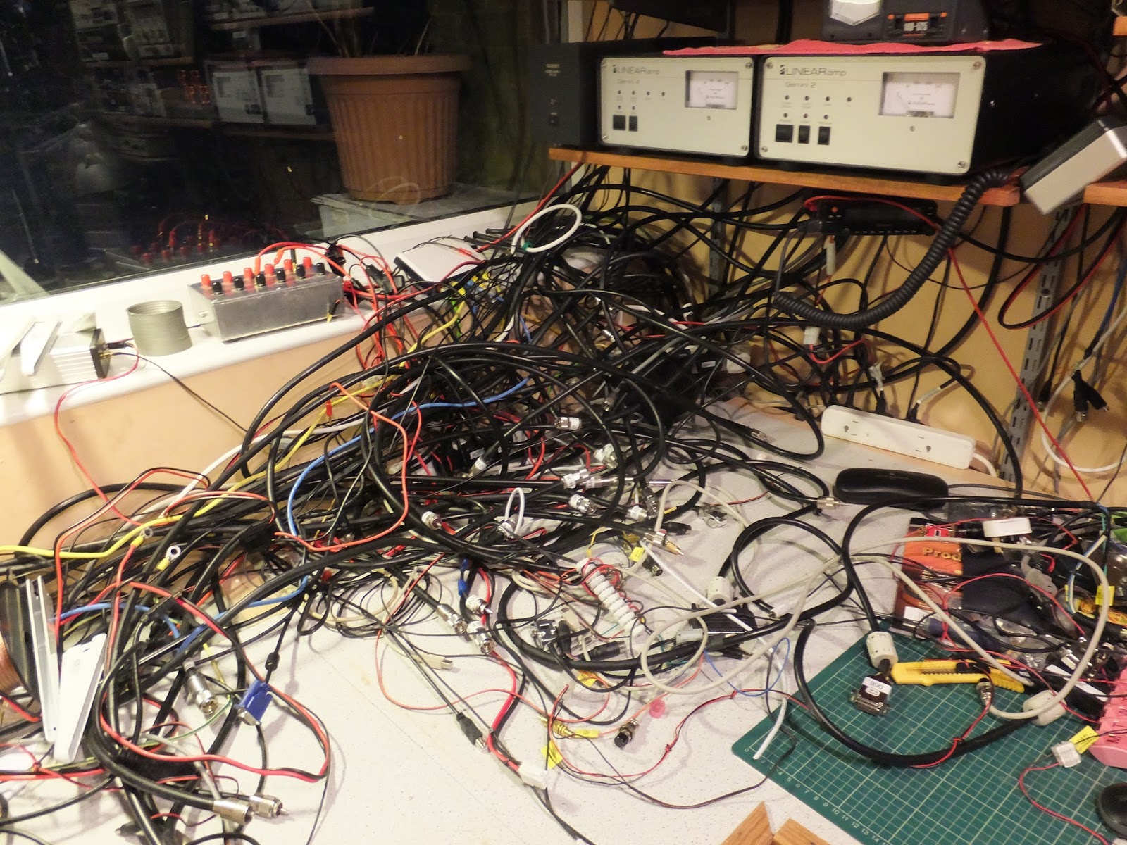
The new shack is finally taking shape:


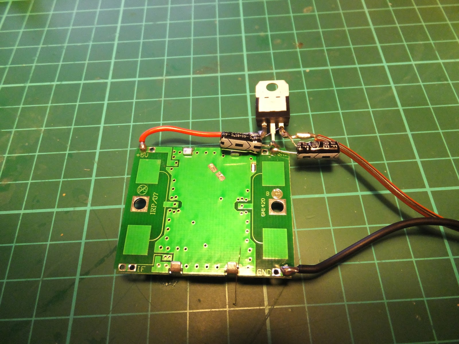
Some new bits n bobs too, new 'scope:


And also found this old Marconi Powermeter on my travels:


This was complete with waveguide to N-Type transition, attenuator and power head. A very nice addition to the test gear setup here. All I need to do now is learn how to use it!
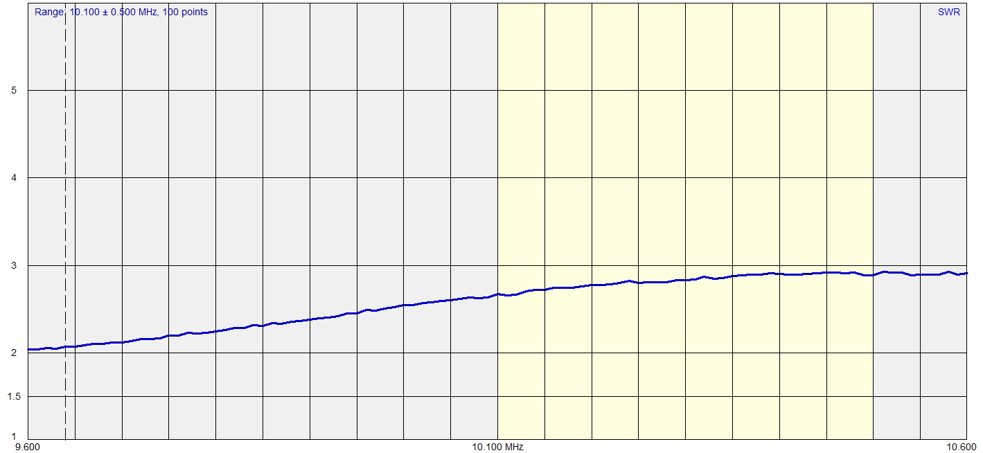
Local conditions...

Tuesday 17 November 2015

MB6GX - Experimental Wires-X Node

Well,

In my new shack I have set up a dedicated Wires-X internet gateway.

I hold two internet gateway NoVs; MB6GX for 2M and MB6IGX for 70cm. As the 70cm NoV stipulates that there is no unattended operation allowed (not even if I am in the house but asleep), I have opted for the 2M Node.


So, MB6GX is on-air and is an experimental Wires-X node in IO93GA on 144.8375 MHz; reports very welcome.

Fun egh?

Monday 16 November 2015

Shack Move!

Well,

Do you ever take on a job and then regret it way before it's done? Here's my shack (old):


So it's basically destroyed!

Here's the new taking shape:


Cats already playing "shelf swat":


Local conditions. 

Saturday 7 November 2015

Repeater Filter

Well,

You may remember last time I mentioned we were setting up a repeater.

I've come home from some work related travels to find the duplexer for the repeater at the house. It looks like this:


I've hooked it up to the spectrum analyser to see what the frequency response looks like, here's the result:


It's impressive, isn't it?

Sunday 25 October 2015

A repeater, Really?

Well,

Whilst musing at the recent HamFest myself and my chum Vince, G0ORC decided it might be a good idea to learn something of the new System Fusion technology.

Having studied a repeater coverage map and concluding there was nothing near us, we decided that the best thing we could do was to put a repeater on the air.

This started the application process for GB3BP a 70cm System Fusion repeater.

We spoke to our friends at LAM Communications and they agreed to sponsor the repeater and provide the Yaesu DR-1XE we need.


So far we have frequency clearance for Input 438.4875 MHz and Output 430.8875 Mhz, and we are waiting for the NoV from Ofcom. We also need to purchase a Duplexer and it's looking like this is the one for the job:


More to follow, but we should be up and running soon.

This page includes the calculated coverage map which looks very pessimistic to me:


and here is a page I have setup for the repeater itself:


Fun egh? Local conditions.

Thursday 22 October 2015

Antennamabob Swap

Well,

Having played with the antenna I installed back here  for a while now, I have decided to go back to the Cushcraft MA5B that I had previously.

I have found that the Q52 antenna had little or no front to back, furthermore there was a switch on the control box that was supposed to "remove" the reflector to make the two element antenna into a dipole, whilst this altered the SWR very slightly, I found no difference whatsoever to signal strength from the front or the back of the antenna. Extended tests in both dipole and beam mode showed no signal strength difference from the front or the back of the antenna. Tom, N6BT, for reasons only be-known to him, chooses to ignore my email requests for technical support - so I haven't been able to get any. I did climb a ladder and conferm that I could hear the relays going click in both the director and reflector when the band switch was altered on the control box, I also double checked the control box to antenna wiring - not sure what else I can do to test the setup.

More recently, 500W of CW to the Q52 antenna has caused the relay box on the driven element to fail. Investigation shows that there are signs of arcing on the element connections - this antenna has proved to be a very expensive mistake!

I have also been having some concerns recently over the amount of weight on the mast and it's ability (or inability) to hold everything. I've therefore designed myself a new mast arrangement, there is no telescoping in this design, but it's much stronger and sturdier (and heavier) than the previous arrangement.

Here we are in the midst of the swap:


The Base section of the mast is 2.5 inch, thick walled box Aluminium, and that is then topped with a 48.3 mm OD stainless steel tube to the rotator cage. The stainless tube drops into the box section with a 2 meter overlap - the two items are bolted together in opposing angles so it can't move or turn. The rotator cage is made from galvanized steel and was manufactured by Tennamast. The stub mast is currently a 48.4 mm OD steel scaffold pole, but I have ordered a 3 meter long aluminium replacement to try and reduce the weight a little.

The mast all pivots and is lifted into the vertical using a winch and steel cable.


Once I have the replacement stub mast I will put back the VHF antennas and all will be well. The rotator is a replacement and is the G-1000 from Yaesu.

Here are the SWR curves from the MA5B as installed:


local conditions.

Friday 16 October 2015

Well, What did you win?

Well,

Look what's just come through the post:


Local conditions.

Good, egh?

Wednesday 14 October 2015

Its a funny old world

Well,

I have a good relationship with the chaps at LAM Communications in Barnsley. I received a parcel from them today which was addressed thus:


Which was fairly amusing....

I have also recently done a video for them on Digital Modes and the FT-991 which can be found here:


Good egh? Local conditions.

Thursday 1 October 2015

A Starter for 10GHz - RX Test

Well,

Myself and Vince, G0ORC headed to Alport today:


We aimed the antenna at the Leicester repeater GB3LEX on 10368.955MHz and here's what we heard:


It was rather foggy, but an excellent site that we will certainly visit again:


Whilst a very feeble distance:


This feels like one of my greatest achievements to date!

Local conditions.

Monday 28 September 2015

Nearly Done - Starter for 10GHz

Well,

The final parts have fallen into place today. Firstly I have adjusted the HB100 from the ARRL $25 10GHz signal generator I mentioned last time to be as close to 10.368 GHz as possible using the LNB range extender for the Spectrum Analyser (also from last time).

The metal case contains a grub like screw underneath a QC sticker. Here you can see the device with the QC sticker removed. As luck would have it the trimmer for the coils in the transverters fits perfectly - you just turn the screw to adjust the frequency:


The other thing I have done is construct an interface box for the FT-817 to:
  • Putting the 3cm transverter into TX by sending DC up the IF coax;
  • Providing a AFSK digital mode interface from my laptop;
  • Giving a CW keyboard capability.
Here's the schematic:


Please note that the 'DC up the coax' bits are entirely stolen from here: http://www.g3pho.org.uk/

The actual device looks like this:


and it interfaces to the FT-817 through the two rear sockets for ACC and PKT.

So all in all I think I now have a CW, SSB and digital mode capability on 10 GHz.


Local conditions.

Sunday 27 September 2015

More Testing - Starter for 10GHz

Well,

You may recall a while ago I started a microwave project called "A Starter for 10GHz" and I did some basic testing of the RX here. Today I have been to visit Peter, G3PHO and his amazing emporium of test gear; together we have tested the TX side of the project successfully.

I've done a few other things since I came back from visiting Peter - the first being to devise a way to get my DC to 1.5GHz spectrum analyser to display 10GHz signals following some excellent inspiration from Peter.

Here's a picture of a eBay purchased LNB:


This device is very high specification and uses a PLL local oscillator, here's the spec (in German) from the box:


So basically it's designed to receive 10.7 GHz to 12.75GHz with a local oscillator of 9.75GHz. If you inject a tone to the DC supply you switch to the 10.6 GHz local oscillator also available, but we don't want that for our purpose.

Now, I've made a very simple Bias-T to send some DC up the coax feed to the LNB:


and used this to connect the LNB to the input of my Spectrum Analyser:
 

Very much inspired by the ARRL $25 10GHz Signal Generator I purchased a couple of the HB 100 units from eBay for a few $s. I have added a voltage regulator plus a couple of caps:


This is switched on and running on the bench as is BTThing I told you about back here. BTThing is set to 2592 MHz making the 4th harmonic at 10.368 GHz.

The Spectrum Analyser screen looks like this:


The smaller peak to the right is BTThing. Doing the maths, we have:

Which is pretty damn close to the 4th harmonic calculation of 10.368 GHz.

Using a similar technique:

We can deduce that the HB100 $25 ARRL signal generator is on 10.345 GHz.


Local conditions. All good egh?

Wednesday 16 September 2015

Windom Test - Shhhhh

Well,

Following the build of the Windom Antenna, I wanted to see if it was functioning, my primary band of interest was 80M. I left the TS-590 WSPRing on 80M last night and here is the result:


Looks like it works.

Local conditions.

Monday 14 September 2015

Baluns - Yet Again!

Well,

Part of the Windom I made last time here was a 4:1 balun. Now I tested one of those way back in time here. Back then I didn't much like what I saw as the frequency increased - it looked like the balun was only good to about 4MHz.

I came home with one of these the other day:


I bought in from LAM Communications in Barnsley.

Now, I repeated the tests I did way back when on this new balun and got more or less exactly what I expected. Here I am inputting a signal at 2MHz into the balun and looking at the two signals out. My expectation is that these two signals should be 180 degrees out of phase, as they are here:


The yellow and blue are the two outputs and the purple the difference between the two.

Now, as I increased frequency the last time I tested a balun this picture got very much "out of bonk" (a technical phrase meaning broken) with the phase difference between the signals moving significantly. On this balun all seems well at 25MHz and higher:


So - this balun seems to have good performance over the advertised range of frequencies - much better than the last one I tested!

As a consequence this is the balun installed on the new Windom.

Local conditions.

Saturday 12 September 2015

Another Windom, Really?

Well,

Having been thinking a little about my antennas I decided to take down the wire dipoles I have for 40M and 30M and try and squeeze in a full size Windom. It has fitted in the garden but the configuration is a little strange! It's kind of in a square where the feedpoint is in one of the corners.

Here's the dimensions of the antenna:


And here are the SWR readings I am getting in the shack starting at 80M:

40M:
30M:
20M:
17M:
15M:
12M:
10M:

So, all in all it looks quite promising! Time will tell as band conditions have been appalling over the past few days.

Here's a picture of our Elmo as he returned from the groomers yesterday - he was suitably unimpressed!


 Local conditions.