
Well,
Been fiddling some more in the shack today with the 70MHz linear amplifier that I am building. The first total screw up was that I need to make an input attenuator so I can drive with a 10W ish input signal and reduce it to about 2W to the amplifier module.
I used an on-line attenuator calculator to design the pad and purchased some suitably power rated components for the job. I soldered it together and then measured the attenuation with the Spectrum Analyser, here with a single fixed frequency output from the tracking generator:

Now, this looked very much like it was about a mile from my target value of attenuation of 7dB and I seen to have more like 20dB at 70MHz. This didn't make much sense.
So I stuck it on my return loss bridge I made back here:
http://g0mgx.blogspot.co.uk/2013/09/so-whats-happened-to-bridge-then.html
to see what the input match to 50R was. Here's what I saw:

Now, this is telling me that at 50R impedance the input SWR to my attenuator at 70MHz is 23:1 (ish) i.e. a complete load of dingos kidneys.
If I just connect a 20dB attenuator (much lower power rated) I made a while ago, I see this:

This one was only really built with HF In mind, but still the SWR at 70MHz is a respectable 1.2:1.
So - why is this attenuator I have made so pants? I now realise that the resistors I bought to make the attenuator are wire-wound rather than carbon. So we have buckets of inductance as well as resistance. That just won't do at all!
Whilst I was messing about with the attenuator I decided it would be a good idea to box the 70MHz TX converter I started to make here:
http://g0mgx.blogspot.co.uk/2012/07/mixing-better-than-before-70mhz.html
and then revisited recently here:
http://g0mgx.blogspot.co.uk/2013/12/testing-times-for-my-linear-project.html
Well, I made an output amplifier for it to raise the output level a bit and have boxed it with it's own PSU:
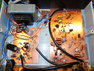
Clearly this should be built into a metal case but I only have this plastic one which will have to do. I must be aware of external RF when I am using it that may make the output wobble somewhat:

The output looks OK on the scope:

but if I were to use this as a TX converter and put the signal on-air I clearly need another low pass filter post the output amplifier I added as the harmonics are quite high:

So, another box for the shelf and a failed attenuator build.
You win some, you lose some.
Been fiddling some more in the shack today with the 70MHz linear amplifier that I am building. The first total screw up was that I need to make an input attenuator so I can drive with a 10W ish input signal and reduce it to about 2W to the amplifier module.
I used an on-line attenuator calculator to design the pad and purchased some suitably power rated components for the job. I soldered it together and then measured the attenuation with the Spectrum Analyser, here with a single fixed frequency output from the tracking generator:

Now, this looked very much like it was about a mile from my target value of attenuation of 7dB and I seen to have more like 20dB at 70MHz. This didn't make much sense.
So I stuck it on my return loss bridge I made back here:
http://g0mgx.blogspot.co.uk/2013/09/so-whats-happened-to-bridge-then.html
to see what the input match to 50R was. Here's what I saw:

Now, this is telling me that at 50R impedance the input SWR to my attenuator at 70MHz is 23:1 (ish) i.e. a complete load of dingos kidneys.
If I just connect a 20dB attenuator (much lower power rated) I made a while ago, I see this:

This one was only really built with HF In mind, but still the SWR at 70MHz is a respectable 1.2:1.
So - why is this attenuator I have made so pants? I now realise that the resistors I bought to make the attenuator are wire-wound rather than carbon. So we have buckets of inductance as well as resistance. That just won't do at all!
Whilst I was messing about with the attenuator I decided it would be a good idea to box the 70MHz TX converter I started to make here:
http://g0mgx.blogspot.co.uk/2012/07/mixing-better-than-before-70mhz.html
and then revisited recently here:
http://g0mgx.blogspot.co.uk/2013/12/testing-times-for-my-linear-project.html
Well, I made an output amplifier for it to raise the output level a bit and have boxed it with it's own PSU:

Clearly this should be built into a metal case but I only have this plastic one which will have to do. I must be aware of external RF when I am using it that may make the output wobble somewhat:

The output looks OK on the scope:

but if I were to use this as a TX converter and put the signal on-air I clearly need another low pass filter post the output amplifier I added as the harmonics are quite high:

So, another box for the shelf and a failed attenuator build.
You win some, you lose some.


