Search This Blog

Radio Guy Tees

Radio Guy Tees
Radio Guy T-Shirts
Showing posts with label IC-9100 23cm. Show all posts

Sunday, 30 October 2016

The SWR tripping issue

Well,

You may recall that back here I was starting to construct the SWR trip mechanism for the 23cm linear I built back here.  I've finished this and tested it today; as soon as the RF level on the reflected port reaches 10.8dBW my amplifier trips.

It looks like this in reality:


The return loss bridge is connected to the ANT socket of the linear and the forward and reflected ports are connected back to the amp box with SMA leads. Inside the box is the RF detector board that converts the RF into a -ve voltage and that has been adjusted in accordance with the calculations I did back here. So assuming the maths was correct I the linear will now trip if the SWR exceeds 1.8:1.

I also note there is good propagation on 2M today; looking out the window I see slightly misty but very still weather, often a sign on tropo:


The situation with Chopsey (AKA Git Bastard Cat from Hell) using my desk as his bed is now completely out of hand:
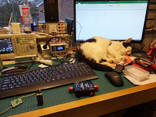


Florrie the ham cat has also taken to sleeping terribly close to my nixie clock which I am very fearful for:


Local conditions.

Saturday, 22 October 2016

Tripping over SWR

Well,

I've been thinking some more about the linear for 23cm I started back here, and more importantly how I can generate a high SWR trip signal for the control board.

I have one of these directional couplers:


It has a forward and reflected port at -30dB. Then I remembered I had one of these kits, which built looks like this:


This will turn the sampled RF into a -ve DC voltage for the SWR trip on the control board.

Now, fortunately or unfortunately we now need to do some maths to determine the attenuation needed. The RF detector board contains two samplers, I have configured one for the forward power and one for the reflected.

So, starting with the forward port:

Assuming a maximum output from the linear of 150W, we can convert that to dBW using:

So my 150W RF becomes 21.8 dBW. Therefore the maximum power at the forward port of the directional coupler is 21.8 - 30 = -8.24 dBW.

Given that the maximum input power to the detector part of the board needs to be 3mW or 0.003 W we can also calculate that 3mW = -25 dBW.

Therefore I need an attenuation of the difference which is roughly 16dB.

Then assuming a trip level of 1.8:1 (or about 10dB return loss) the reflected levels need to be 10dB down from the forward so an attenuator of 6dB is needed on the reflected port.

Using my signal generator at 1,000 MHz (1 GHz) and adjusting the output we find this is the response of the board:


So it all looks pretty good.

I now need to do some reading up on how I can drive the trip alarms on the control board, but this should do the trick nicely.

Here's the dogs doing what dogs do:


Local conditions.


Wednesday, 19 October 2016

Wow - It's working then?

Well,

A couple of updates for you.

Firstly I ordered a 13cm 44 ele antenna, which duly arrived:

I suspect this one is designed for beaming round corner:

Not very clever!

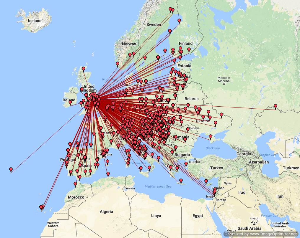
Secondly, I was looking at my 6M logs recently and decided to create a map of my 6M contacts:


I just need that elusive USA opening!

Here's the 23cm amplifier I mentioned back here. It's finished now - I tried it on the air last night in the UKAC and received some good reports:


It's even wired quite neatly inside:


Cabinet feet and everything:

I'm really quite pleased with this. Local conditions.

Saturday, 9 May 2015

The Tigertronics Signalink USB

Well,

Following my frustrations with the Yaesu SCU-17 rig interface back here:

http://g0mgx.blogspot.co.uk/2015/05/whats-going-on-here-then.html

and more here:

http://g0mgx.blogspot.co.uk/2015/05/whats-going-on-here-then-part-ii.html

I've been fiddling today with a Signalink USB interface. This suffers from similar issues to the Yaesu device, but there are a couple of excellent internet resources that help you fix it, here:

http://www.frenning.dk/OZ1PIF_HOMEPAGE/SignaLinkUSB-mods.html

and here:

http://www.k7sfn.com/projects/signalink.html

So here is my Signalink half way through the fiddling process:


One of the most important mods in the link above is the replacement of a cap on the board with a 33uF value component. My Signalink already had 33uF onboard so this was left as-is.

What I have done is (documented on the links above), firstly added a 4.7uF capacitor to the power rails for the internal PIC:


I have also removed the 1K resistor feeding the audio circuitry power and fed the supply via 470R and the orange jumper wire you can see. This takes the power from the PIC regulator rather than the dirty USB supply. I have also added 47uF tantalum capacitor to the USB power supply:


That has improved the audio response dramatically and here is what we see post modification:


Now, the Signalink doesn't include an FSK switch to run RTTY, so I have modified the rig -> Signalink cable to bring the FSK keying line to an unused pin on the DIL internal socket, and wired that through a 4N32 opto-isolator to a 9 pin D-type connector I have added to the unit:


This connector can now take a Serial-USB adapter so I can run FSK from the PC.

I've also sold my FT-DX5000 and bought an ICOM IC-9100. I have fitted the optional 3KHz roofing filter and the 23cm module in the radio:


Freddie Cat can't be comfy here, but has been supervising most of the day:


Local conditions.