
Well,
You may recall the 50/70MHz linear that I last reported on back here:
http://g0mgx.blogspot.co.uk/2013/12/70mhz-linear-progress-is-steady.html
The first thing I need to do is to test the main amplifier block to confirm all working as planned. Now, to do this I need a fairly accurate 70MHz signal to amplify - the problem is that the signal generator I made back here:
http://g0mgx.blogspot.co.uk/2013/10/so-hows-sig-gen.html
doesn't go that high.
Some of you may recall when I first started meddling with 70MHz that I made an experimental 70MHz transmit converter to take a 10MHz signal and mix it up to 70MHz back here:
http://g0mgx.blogspot.co.uk/2012/07/mixing-better-than-before-70mhz.html
So I have dug that board out again, dusted it off and straightened a few bits that had got bent in the draw and stuck some power on it. I have the signal generator at 10MHz connected to the RF in port:

So in the picture above we have a 60MHz local oscillator and associated amp and filter along the top of the board, the connector on the RHS has the 10MHz signal from the signal generator then there is a diode doubly balanced mixer feeding another amp and output filter along the bottom. The output of this looks like this on the Spectrum Analyser:

And here on the 'scope:

It's important to understand that the Spectrum Analyser is a 50 ohm instrument - the 'scope isn't - hence the 'scope is terminated in a 50 ohm feed through you can see in the picture below:

So, using the data from the 'scope (which I suspect isn't too accurate at 70MHz) we can do some maths to calculate the power out of this concoction:

So, using the peak-to-peak voltage reading from the 'scope I get a power reading of about 1dBm. So, let's now connect the signal to the accurate power meter I built back here:
http://g0mgx.blogspot.co.uk/2012/11/the-art-of-calibration.html
And this is what I see (apart from a stupidly bright power light):
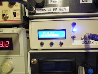
and if I set the reference level on the Spectrum Analyser to 10dBm this is what the signal looks like:

So it looks very much like a 0dBm signal at 70MHz to me.
All this test gear is really coming together- I trust the dBm meter I made very much - a great deal of effort went into calibrating it and there is no reason it should deviate from it's set up.
So now I need to hook up some power to the amplifier brick, terminate it through a power meter to a dummy load, throw the switch and see what happens.... watch this space.
Good, egh?
You may recall the 50/70MHz linear that I last reported on back here:
http://g0mgx.blogspot.co.uk/2013/12/70mhz-linear-progress-is-steady.html
The first thing I need to do is to test the main amplifier block to confirm all working as planned. Now, to do this I need a fairly accurate 70MHz signal to amplify - the problem is that the signal generator I made back here:
http://g0mgx.blogspot.co.uk/2013/10/so-hows-sig-gen.html
doesn't go that high.
Some of you may recall when I first started meddling with 70MHz that I made an experimental 70MHz transmit converter to take a 10MHz signal and mix it up to 70MHz back here:
http://g0mgx.blogspot.co.uk/2012/07/mixing-better-than-before-70mhz.html
So I have dug that board out again, dusted it off and straightened a few bits that had got bent in the draw and stuck some power on it. I have the signal generator at 10MHz connected to the RF in port:

So in the picture above we have a 60MHz local oscillator and associated amp and filter along the top of the board, the connector on the RHS has the 10MHz signal from the signal generator then there is a diode doubly balanced mixer feeding another amp and output filter along the bottom. The output of this looks like this on the Spectrum Analyser:

And here on the 'scope:

It's important to understand that the Spectrum Analyser is a 50 ohm instrument - the 'scope isn't - hence the 'scope is terminated in a 50 ohm feed through you can see in the picture below:

So, using the data from the 'scope (which I suspect isn't too accurate at 70MHz) we can do some maths to calculate the power out of this concoction:

So, using the peak-to-peak voltage reading from the 'scope I get a power reading of about 1dBm. So, let's now connect the signal to the accurate power meter I built back here:
http://g0mgx.blogspot.co.uk/2012/11/the-art-of-calibration.html
And this is what I see (apart from a stupidly bright power light):

and if I set the reference level on the Spectrum Analyser to 10dBm this is what the signal looks like:

So it looks very much like a 0dBm signal at 70MHz to me.
All this test gear is really coming together- I trust the dBm meter I made very much - a great deal of effort went into calibrating it and there is no reason it should deviate from it's set up.
So now I need to hook up some power to the amplifier brick, terminate it through a power meter to a dummy load, throw the switch and see what happens.... watch this space.
Good, egh?


