Search This Blog

Radio Guy Tees

Radio Guy Tees
Radio Guy T-Shirts

Saturday, 31 December 2016

The VLNA, Oh Boy!

Well,

I think I have finished the build of the VLNA for 13cm; having constructed the project I am wishing I had bought a ready built and aligned unit. This was the hardest project to date, mainly because of the very tiny components. I really struggled to get the input matching network parts in place - and have no test gear to actually measure the return loss or noise figures of the final build.

It looks like this:


You can see the input network components in the image above; it kind of looks like the instructions from G4DDK @DXING, but I have no means to actualy measure or test the input return loss.

Lets see.

Friday, 30 December 2016

Busy, Isn't it?

Well,

Following my Top Band anteanna from last time, here's a WSPR map:

I find it all rather hard to believe.

Local conditions.

Wednesday, 28 December 2016

Top Band (Again)

Well,

A while ago we had some work done in our garden, this resulted in the removal of a 'purglar'; now, this was all fine except it was supporting my top band antenna I made back here.

I've got round to making a replacement for the antenna today, nothing original - it's an end fed sloping, inductively loaded wire.

There's 54 feet of wire, 20 turns on a bit of tumble dryer vent pipe, then 5 feet to the feed point plus an earth rod (well two actually) on the sreen of the coax. Here's the inductor:


and this is the earth arrangement:


Now, I am planning to add several long counterpoise wires, but I haven't done so yet. I connected the antenna to my analyser thingamabob:

or if you prefer return loss:


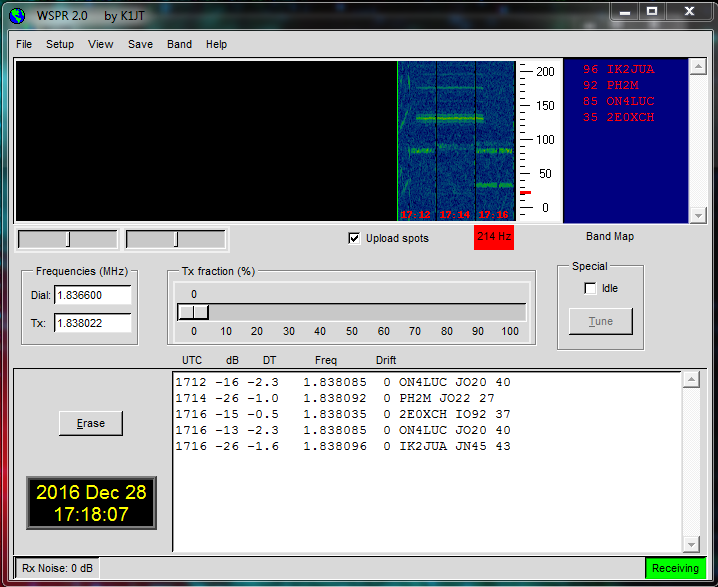
I've been listening on the WSPR frequency tonight:


It will be a very inefficient antenna and also it has a very narrow bandwidth (like all inductively loaded antennas), but it's clearly hearing signals.

Here's a map after an overnight run:


I also took down the main 4M and 6M antenna today for maintenance, I've put somthing I had at the back of the shed in it's place temporarily, I've also put the 13cm antenna I had lying on my bench in the air:


Here's our two doing what Spaniels do on a beautiful frosty morning earlier today:


Good, egh?

Tuesday, 27 December 2016

More Sequencing Secrets

Well,

I've added a FET switch to the sequencer I made last time. The FET switch will provide +12V on RX to the masthead and will be used to switch the masthead relay and also power the VLNA.

The schematic looks like this:


and it's built on the same bit of veroboard as the sequencer:


It switches very quickly, here in blue is the PTT being enabled and in Yellow the power supply that will head up the mast:


So we will then have 200+ ms delay before EVENT 1 from the sequencer:


which will be used for things like turning on the PA bias and enabling RF 'n' stuff like that.

All in all this is coming on nicely.

Local conditions.

Monday, 26 December 2016

Sequencing Secrets

Well,

I've been thinking some more about the 13cm project I have on the go, more importantly how I am going to arrange all the bits together.

Firstly we have a 13cm VLNA from G4DDK. I've started the build of this project - this is extreme soldering! the bits are very tiny indeed.

Here's where I am at with the project, unfortunately the last chip cap has made a bid for freedom and is in the carpet somewhere. Here partially built:


and here, almost complete all bar the input components:


Now, I also have the transverter from back here plus a ex telecoms PA that I will start to modify later.

I've started to draw the setup, to save on relays, switching and the associated losses, I will run separate feeds to the antenna (or masthead) for TX and RX. Also, due to the complexities associated with bias-T at these frequencies I will also feed power by cable.

I think it needs to look something like this:


So the thing labelled "gubbins" in the diagram above is actually a sequencer. Having built my 23cm amp back here utilised a ultimate amp control board from W6PQL, that included a sequencer and I had the schematic. So I drew this using non SMD components:


In reality it looks like this once built:


Looking at the top of C1 with a 'scope and grounding the D1 PTT line, we see this:


and as the voltage in C1 rises so the difference between the inverting and non-inverting inputs of the four op-amps swap in sequence as the voltage climbs to the power rail. Here you can see the output state change of the Event 1 op-amp in blue against C1 in yellow:


Event 2 happens later and then event 3 and 4. You can also see that they revert back in the opposite order as the voltage in D1 falls when the ground is removed from D1 and the capacitor discharges through D2 & D3.

Here's the timne delay from PTT to Event 1:


Those in the know tell me that these coax relays can bounce, so a delay of 200ms or more may be needed from thr relay power being initialised to any RF heading that way.


More to come!

Local conditions.

Wednesday, 21 December 2016

QRSS Beacon

Well,

Earlier on today I dug out an old QRSS beacon that I made for 30M. I plugged it into my 30M dipole and switched it on.

I've just found this on the internet:


This is from the live grabber belonging to LA5GOA, here I have annotated the image to highlight my callsign in the grabber:


The beacon is running about 6V Peak to Peak which is around 100mW. Clearly I need to turn the power down.

Local conditions.

Measuring 13cm

Well,

Following my previous musings here and the RX tests I have done on the 13cm transverter, I had a bash at testing the TX function today.

I found a frequency counter and RF power meter on my travels recently; Its an XL Microwave counter that measures up to 20GHz.

I've cobbled together a directional coupler from Narda, a Marconi 20dB attenuator plus a further 15dB reduction from another on-line purchased coupler. All in all the frequency measurement point should be about 35dB down from the actual output from the transverter.

It all looks like this:


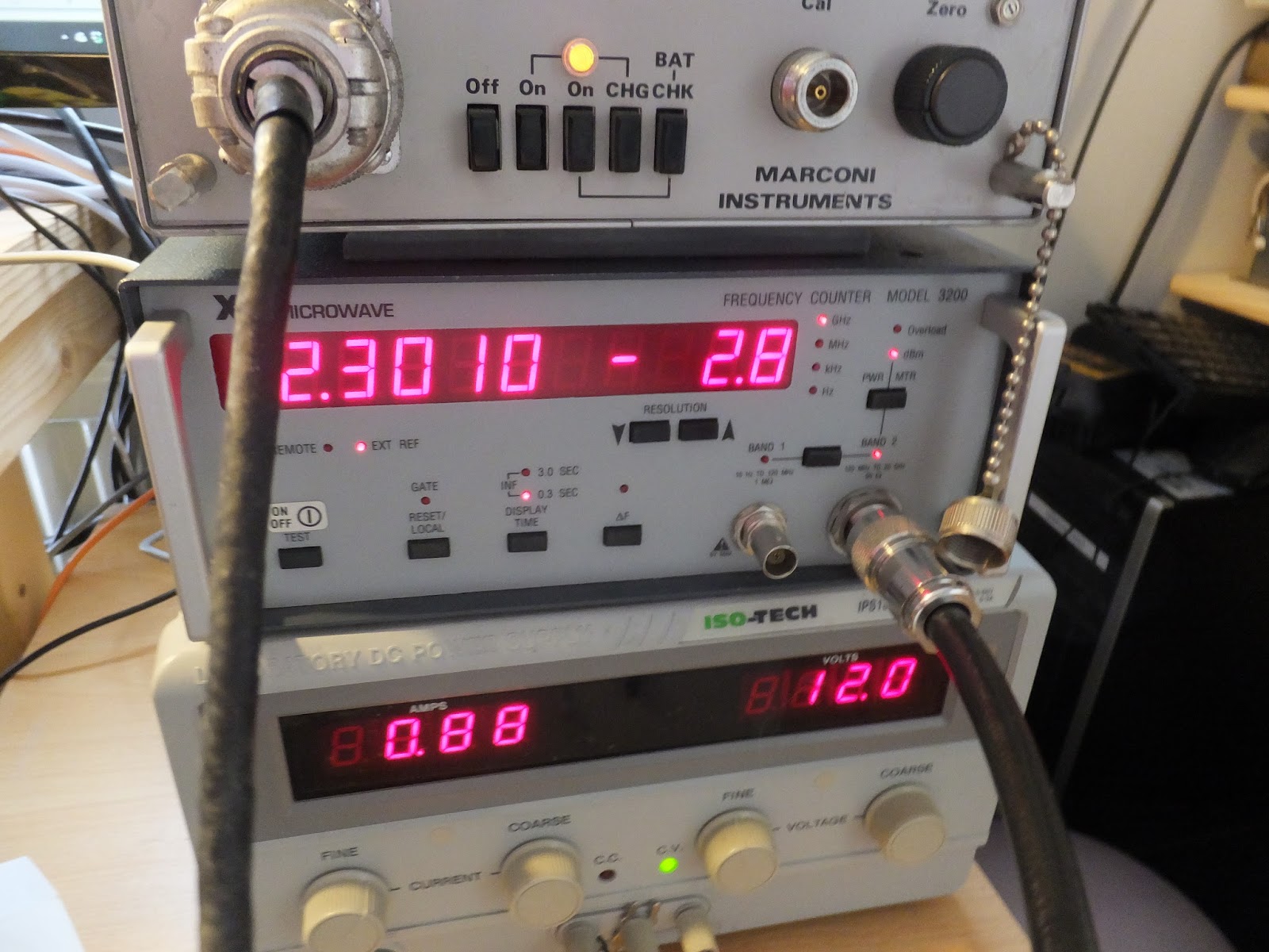
Using the new meter and counter I am measuring exactly 2301 MHz and a power of -2.8dB:


So assuming my 35dB of attenuation is there or there abouts, that means the output of the transverter is about 32-33dBm which is about 2W - exactly on the money.

My analogue power meter also reads about on the money too:


I've also taken the -30dB forward port from the Narda directional coupler, mixed it with my 900MHz frequency generator as described back here. This has allowed me to see the output from the transverter at 2301 MHz - 900 MHz = 1401 MHz:

All good, egh?

Here's our beautiful Pepper Cat: