For some time I've run an ADSB receiver here called PiAware - It's by flightaware, runs on a Raspberry Pi and uses an RTL dongle and a short bit of wire wedged in the shack window as an antenna - not the best.
Today I've been making a better antenna, a masthead amplifier and checking for improved reception. I recorded my musings as a video:
I paid a visit to fellow ham and insane constructor Ian, G4EVK; who has some amazing model making equipment and a good plumbers blowtorch!
Here's some photos of the build:
I'm waiting for a "rocket" LNB that I hope will fit on the end of the waveguide (read 22mm pipe) using a compression fitting, I have also used the trick from here to check the 2.4GHz return loss - after a little bit of bending it's now looking spot on.
Yesterday I very nearly mowed the lawns, today we woke up to this:
Let it snow.....
** UPDATE **
I have used the lens from a "rocket" LNB on the front of the feed and removed the feedhorn from an Octagon LNB (with a hacksaw) and connected it all together with a 22mm compression pipe connector and some waterproofing with some silicone. I have also modified the LNB to take an external 25MHz signal (as above):
I've used the same trick I used back here to measure the return loss on 2.4 GHz and its around 20dB; I have also lashed up the receiver on the 10GHz downlink and that is working just fine.
Now, how on earth can I weather proof this?
Miss Maggie and Miss Pepper Cat seem to be economising by using the same bed? Bonkers.
I've stuck it on a dish I had lying in the hedge and attached it to an Azimuth and Elevation rotatormabob - you may remember that setup from here.
There's an LVB tracker with computer driven elevation and azimuth control.
I pointed the dish in very roughly the right part of the sky and then tuned around where I expected the signals to be, with the narrow band transponder downlink at 10489.550 - 10489.800. I've subtracted the 9750 local oscillator in the LNB.
I then found some signals and used the rotator controller to peak the signals - I've ended up at 149 degrees to the south and 18 degrees elevation - there will be many, many errors in my setup at thus time.
I'm a bit off frequency, and also drifting a touch. I need to add external frequency lock to the LNB. I've also started to setup an uplink based on the system we made here.
But I've certainly found it:
So the low beacon on the narrow band transponder is sending:
5i 5i 5i de qo-100 BK dl50amsat
and I am receiving this at a constantly drifting down frequency, currently at:
739.306 MHz on my SDR. So I add the 9750 MHz Local Oscillator and we get 10489.306 MHz
If should be between 10489.550 and 10489.555 MHz so I am a bit out of bonk and drifting.
Next job - lock the LNB to a frequency reference!
Much more to follow on this topic!
** UPDATE 1 **
I've modified my LNB to take an external 25MHz frequency - so I can feed it with a locked reference.
This has been done in accordance with the instructions here.
I'm feeding the LNB with some cheap co-ax from Amazon and I have replaced one of the "F" connectors with a BNC and attached it to my Leo Bodnar reference which I have set for 25MHz.
According to the instructions (well, read box) from the LNB:
Model: OQSLG Green HQ
Input: 10.70 GHz - 12.75 GHz
LO: 9.75 / 10.6 GHz (10.6 with 22KHz signal on coax)
0.1dB noise ratio
Gain: 60-65dB
Horizontal 18V; Vertical 12V
Now, with the 25MHz external reference, the low end beacon on the Narrow Band segment of the satellite is exactly on frequency:
I'm still worried about LNB skew as switching to horizontal doesn't null out this beacon completely = not even sure if it should, but I am definitely not seeing the DATV beacon yet so more fiddling is required.
I've had an old Yaesu FT-990 for quite a while; its a delightful analogue radio with very few modern bells and whistles.
Now, I've previously opened up and admitted I suffer with TEAS; I suspect the diagnosis may be wrong and actually it's GAS that I have got (Gear Acquisition Syndrome) it seems to be more far reaching that just test equipment.
I've got myself another FT-990.
There is some logic behind this madness, the ROM version in mine was 1.2 and that doesn't allow CAT control from my logging software. The second radio I have is at version 1.3 which does.
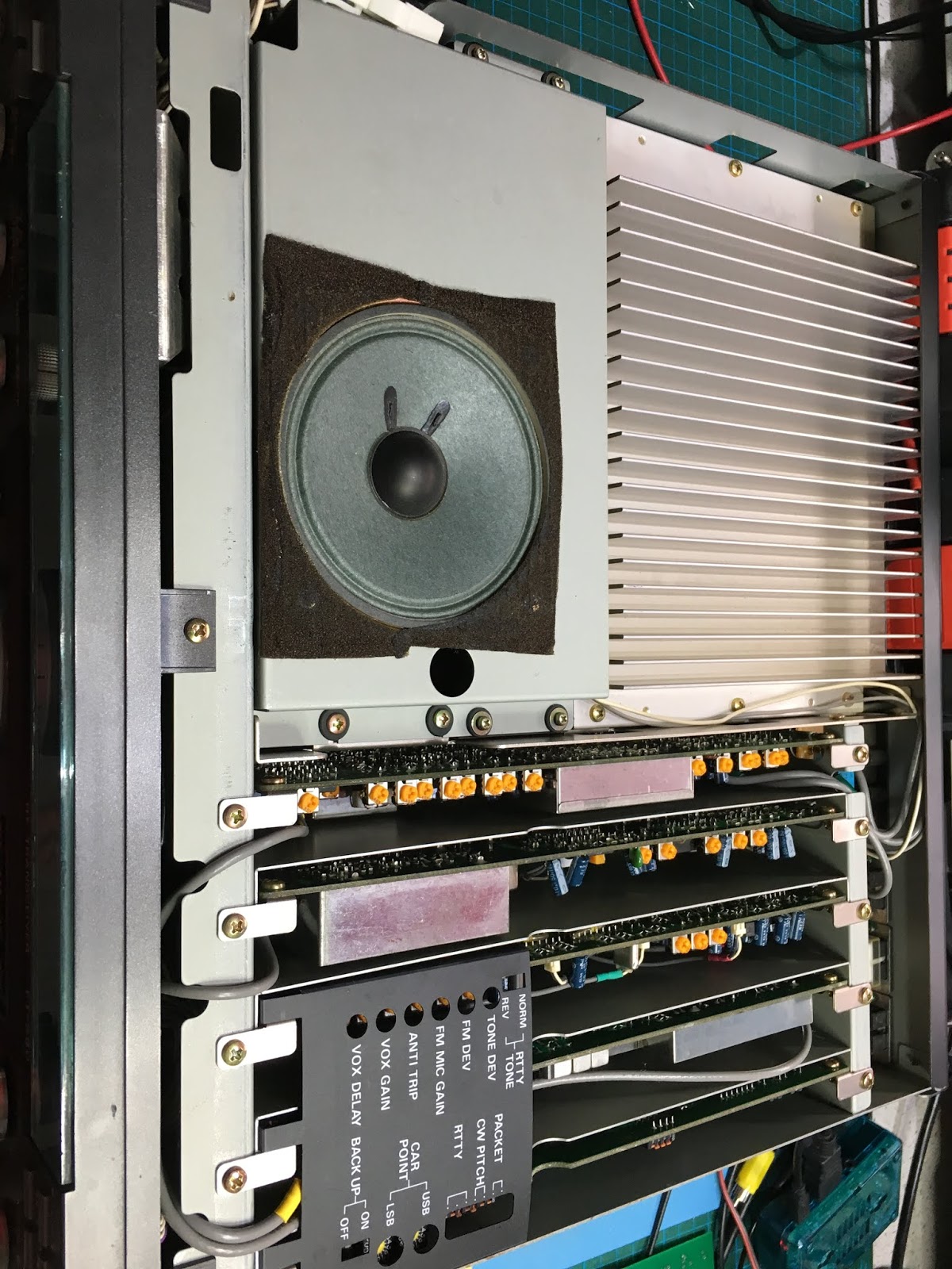
This is the inside of the new rig, which is extremely clean and tidy.
It has two filters fitted, one is an Inrad SSB filter and the second is the wider 500Hz CW filter.
The image below is the "control board" and this contains the CPU and ROM with the software version:
So, all I have done is simply swap these boards between the two radios. I also notice that the one I use on the bench is much dirtier inside. The case on the latest acquisition is a little scruffier so I guess we will stick as we are. I also notice my existing rig has this modification at the back. It's clearly switching am RF path, bit I haven't tried to figure out which one or what it does. There's a relay on the underside of the bit of veroboard and it is doing something under certain unknown conditions. I need to investigate further.
Anyone know what that mod might be?
I'd also be interested in anyone who wants a FT-990 V1.2 ROM fully working. It's only going to gather dust here.