Search This Blog

Radio Guy Tees

Radio Guy Tees
Radio Guy T-Shirts

Friday, 31 December 2010

BITXing Some More

I've just about finished the other bits and bobs for the BITX I was aligning yesterday. I've made a digital dial for the frequency readout and an s-meter; the readout is a kit I have had here for ages, it came from QRP Kits:

http://www.qrpkits.com

The build using surface mount components is really tricky, but it works OK second try!


1st time through I'd got some pins on the main microprocessor chip shorted out which was screwing up the multiplexing of the counter display. You really need to use a magnifying glass to see this stuff properly. Soldering it is another game again! I can't get the camera to take a picture any closer, so you'll just have to believe me when I say the components are small!

I've got all the bits of the BITX V3 wired together on the bench here (the mouse is not an essential part of the BITX):


Now, in a nutshell, what you should be able to see below is exactly what I love about ham radio, you can see the mess above which is all my own work, I turned it on, made a slight circuit modification (connected the speaker) and this is what I soon came across. There's only a piece of wire rammed in the antenna connector right now:


Not bad, egh????

Thursday, 30 December 2010

BITXing

A while ago I ordered a BITX20 V3 (Bi Directional Transceiver) from Sunil in India:

http://www.cqbitx.blogspot.com/

This is a 20M version of the ever popular QRP design of the BITX. There is a lot of information on the BITX design available, originally designed and built by Ashhar Farhan, 2004. The project details are here:

http://www.phonestack.com/farhan/bitx.html.

There is now a wealth of knowledge on the various forms of this original design available at a Yahoo! group here:

http://groups.yahoo.com/group/BITX20/

I was looking for a good drive for my linear amp project and figured I might as well build this project and use this to test the linear!

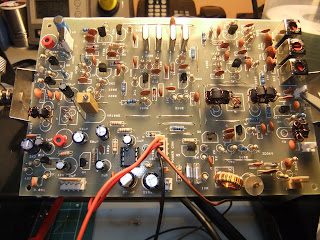
Some pictures of my build follow, generally this was very straightforward, although I have built a different version of this before:


Looking at the output of the PA with a constant drive from my audio generator, I've got about 70V pk-pk (the scope is connected using a x10 probe so it's 20V per division), that's about 8 watts. I would have expected a little better from a single IRF510 MOSFET. I used pk-pk voltage / 2 * .707 to give me RMS. Then squared the RMS and divided by 50 ohms.

So in this case I have 70 / 2 = 35V peak. Multiplied by 0.707 = 24.745V RMS

P = E^2 / R, so thats 20.745^2 = 430.355 / 50 Ohms = 8.607 watts.


The MOSFET is being powered from an unregulated supply of about 26.26V DC which is also being regulated down to 13.8V for the main board and the relays on the PSU/Linear board.

I'm now planning to build a s-meter, a frequency readout and then case this project. The output is looking really clean, so once these extra bits are complete I need to stick it on the air and get some reports!

This kit cost me $40 US plus some very modest shipping costs from India. The kit contains the boards, relays, a hard to find transistor, cables, connectors, torroids, enameled wire plus much more. If you are looking for a cheap and easy way onto 20M, it doesn't get much better than this! All other components needed for the build I had here in the shack already.

Friday, 24 December 2010

Balanced Modulator Musings

I've been fiddling further with the balanced modulator from the SSB exciter in my previous post to try and get some better carrier suppression. The first thing I have done is to match some IN5711's - these were the diodes used in the RadCom article I am copying. These diodes didn't make much difference, so I then decided to remove the balancing components from the circuit and re-wind the toriods. I originally used some FT50-43's as I had loads of these, but I have re-wound the toroids with FT37-43's and much tighter wound trifilar wire.

After all this I still didn't like the output much, so I then tried matching some good old IN4148's and still with no balancing components, and probably a more symmetrical layout:

This is now the output of the crystal filter on LSB:


And here on USB:


You can see that the carrier suppression is now very significant, so I think I am quite happy with this aspect of the exciter now.

The next part of this project will be to make the triple balanced modulator (TBM) as described in January 2011 RadCom. This will need five bifilar wound transformers on FT37-43's which I will need to have a good rummage to find! There is also some discussion on VHF transistors and the selection of the MPSA10 - which it just so happens I have about 100 of!

So onwards with this project over this coming holiday given suitable breaks from family commitments.

More soon.

Monday, 20 December 2010

How to generate drive to generate drive

Or perhaps I should call this post "recursion, see recursion".

I finished testing the phasing of the transformers on the linear amp board, you can see from this pic that the input gets split nicely into two signals that are out of phase with each other. These are effectively the inputs to the gates of the FETs. The output transformer is then doing a good gob of mixing these two signals back together again:


So, this suggests that the transformers are wound and installed correctly. So I've installed the FETs on a heatsync that is a little below the board, that bit's worked out OK I think:


I can bias the FETs as expected, I measured the idle current and then increased the FET bias voltage until each FET drew an additional 10mA, the board with the relay engaged and the FETs both biased on is now drawing about 50mA.

The problem I have now is that the board includes a RF sniffer to close the relay, my signal generator (homebrew of course) only generates about 150mV pk-pk output which isn't anywhere near enough drive to close the relay, if I use a cable to drive the relay (i.e. short out the relevant bits of the circuit), I'm not seeing much gain in the FETs as I dont think the drive is enough for them either.

So I need to build an RF amplifier for my signal generator before I can test my RF amplifier - recursion see recursion.

Hence another small project is born.

Friday, 17 December 2010

HF Linear

Well, yet another project has started today; I've been collecting bits for the WA2EBY amplifier. This design claims 40W from a 1W drive accross all HF Bands. I got the PCB's from Far Circuits in the USA http://www.farcircuits.net, the toroids came as a pack from Kits and Parts in the USA also http://kitsandparts.com/. I've bought from both of these suppliers before and their dispatch to the UK is very reasonable and fast.

I've had to order a load of Silva Mica caps from Rapid electronics in the UK for the Low Pass Filters, as I didnt have anything suitable in stock; they are supposed to arrive today, but aren't here yet.

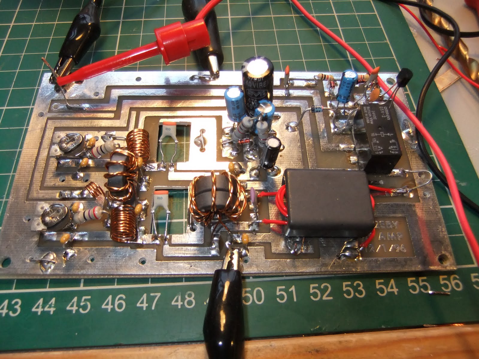
The main amplifier board is going to look a little scruffy, but here are a few picks from the build so far:


The last image shows the board under test, I havent inserted the finals yet and I've just stuck a 1nF capacitor between where the Gate and the Drain will go on each FET. This should allow me to check the phasing of the transformers and the other bits before I smoke any expensive parts! I've just watched the realay explode as I thought it was a 24V coil, but it seems it was a 5V coil and it didn't take too kindly to having 28V accross it!!!

I'll post more when I've got a replacement relay, I don't have one right now.

Would you Adam and Eve it?

Well,

As big a believer in QRP as I am, I'm not sure I'm able to actualy get my head round this. 6V p-to-p out of my QRSS beacon, that's about 100mW. This feeds through my ATU (mainly to convert from BNC to PL259!) then half way round the house in RG213; then up the side of the house and into a Windom.

Here is my call very readable at the QTH of ON5EX, thanks Johan! Thats a whopping 420km distance. Not half bad! The beacon frequency looks quite steady too! I'm well impressed:

Wednesday, 15 December 2010

QRSS Beacon Alignment

I've had a go at aligning this QRSS beacon today. The output from the small transmitter seems very clean and I've set it to the recommended level of just over 6V p-to-p. I did manage to set the output pot completely to max when I first powered it on, lots of heat but no smoke before I realised! I dont seem to have done any damage though...

I've stuch a 50R load on it and a scope probe, here's the output, very clean:

I've adjusted the frequency output to as near as I can to where I want it to be, and I've also watched the output using the Argo software and set the frequency shift of the callsign transmission.

So I guess it's time to connect the antenna and leave it running. There are quite a few grabbers on the internet, so I need to understand that a little more and then find out if and how far my 100mW is getting!