Search This Blog

Radio Guy Tees

Radio Guy Tees
Radio Guy T-Shirts

Tuesday 31 December 2013

WSPRing Again on 80M (Shhhhhhh)

Well,

For the past two nights I have left my TS-590 running an output power of about 20 watts on the 80M WSPR frequency.

Personally I find WSPR a truly brilliant invention and the ability that the software has of pulling very weak signals out of noise simply astounds me. All of the K1JT modes can be considered in the same light - they are pure genius and astound me every time.

Here's the results of the night before last:


and last night:


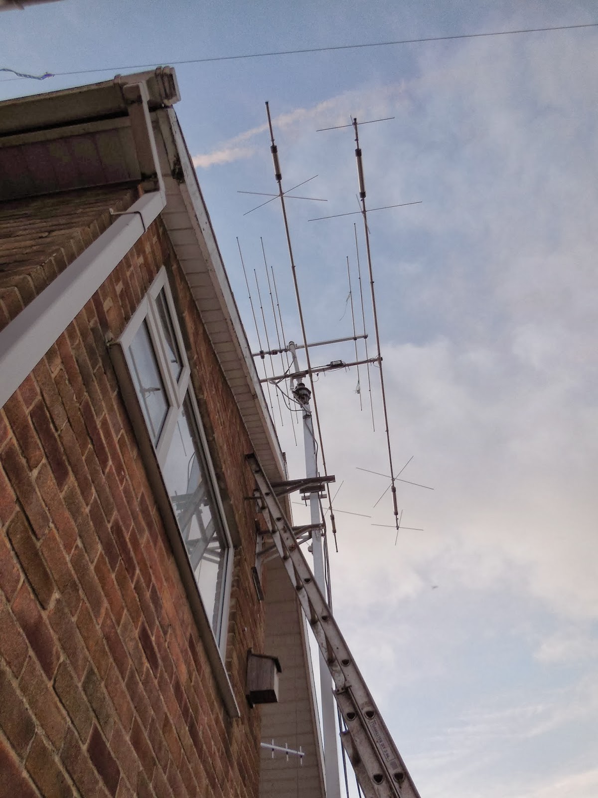
All this using the piece of string I made for an 80M antenna back here:

http://g0mgx.blogspot.co.uk/2013/12/80m-into-43-feet-that-doesnt-go.html

Stunning, egh?

Monday 30 December 2013

QUCS Simulation - You What?

Well,

Been fiddling today with a new piece of software I have found called QUCS - the Quite Universal Circuit Simulator. It's a really neat open source project you can find here:

http://qucs.sourceforge.net/

There is lots and lots to this package, but my interest is in simulation of filter designs. Here, for example, is the design of a 9th Order Low Pass Chebyshev filter for a 4.2MHz target cut-off:


The package will design the filter for you based on your selected parameters but then you can tinker with the values to replace the theoretical calculated values of the components with real ones and then simulate the filter behaviour before and after. Here's the simulation of the filter above:


Now, I need to build the filter and see how close the simulation is to real world, but this looks like a very interesting package that I think will come in very handy indeed!

Good, egh?

Which one do you trust?

Well,

The linear that I started way back here:

http://g0mgx.blogspot.co.uk/2013/11/now-that-smoke-has-settled.html

is almost complete, I've done my best to calibrate the input power detection circuity and will certainly "trip" into an alarm state if I overdrive the amplifier brick. I have also calibrated a simple directional coupler on the output to give me both forward and reflected power indication.

I needed to understand the match that my antenna gives me on 4M, but the Antenna Analyser that I bought some months ago only goes as far as 50MHz and the other MFJ unit that I share with Vince, G0ORC seems to have a gap in the tuning at exactly the 70MHz band.

So, I used the return loss bridge from here:

http://g0mgx.blogspot.co.uk/2013/09/return-loss-bridge-where-does-it-lead.html

and explained how to use it for SWR measurement back here:

http://g0mgx.blogspot.co.uk/2013/10/so-lets-get-bit-smarter.html

So, hooking the antenna from here:

http://g0mgx.blogspot.co.uk/2013/05/thatll-never-work-will-it.html

we see this:


and focusing right on the 70MHz allocation only:


So, whilst it's not perfect, the antenna is a good match across the whole band. As the MS frequency it looks to be 1.3:1 - which is more than acceptable.

I need to introduce you to two new residents at G0MGX, they are Mother and Son, please meet Pepper and Freddie:


Fun, egh?

Thursday 26 December 2013

Honestly? It's a mess!

Well,

I've been boxing the components for the 70MHz linear amplifier that I have been making:

http://g0mgx.blogspot.co.uk/2013/12/testing-times-for-my-linear-project.html

today. The control software is still very much under development, but in my usual build a bit, test a bit fashion, I need everything to be wired to the Arduino processor board now so I can make progress.

All in all, here's the list of separate bits I've ended up with:


  • Linear brick and heatsync
  • 48V SMPS Power Supply
  • 9-0-9 transformer for DC supplies
  • Fan for cooling
  • Veroboard containing the ancillary electronics for the Arduino relay and fan control plus the DC regulators for the +24, +12 and +9 rails
  • Low pass output filter
  • Arduino
  • LCD display
  • Directional coupler for output forward and reflected power reading
  • **huge** coax relay for the output switching
  • input attenuator
  • small coax relay for input switching
  • Current shunt
So all together there is a lot more than I bargained for!

Here's what it looks like today:


and I have to confess that this is one big mess that I hadn't set out to make. It should work OK, but the "junk box" style of part sourcing has resulted in some really bigger than needed bits....

Florrie cat's not been helping much today:

 
Progress, though, egh?

Monday 23 December 2013

Extreme, wow that's Extremely Extreme!

Well,

Thinking about Lindy that I made back here:

http://g0mgx.blogspot.co.uk/2013/12/whos-lindenblad-i-wonder.html

I ordered a 144-145 MHz pre-amp kit from Amsat-UK:

http://shop.amsat.org.uk/shop/catalog/browse

The design was published in September 2012 OSCAR News.

I've done quite a bit of SMD kit building in the past, AKA Extreme Soldering - but this was a whole new challenge! The components in this were the smallest I've ever come across - this was really tricky!


The image above should open in quite high-res so you can see the effort I have made of the soldering. It's quite poor really, but it certainly works as you can see below. The odd looking peaks on the far left of the spectrum are harmonics from my 10MHz frequency reference (I think):


It's already mounted in a die-cast box and the power is fed down the coax. This should work directly with my FT-847 which can provide coax based power to external pre-amplifiers.

I'll have to see how the satellite passes look tomorrow with this amplifier in-line - ideally I should mount this at mast head end of the coax to amplify any signals that are lost in the coax run. I've got about 20 meters of Westflex 103 and the losses at 145MHz are quoted at 4.5dB per 100M. I make that a possible loss of 0.9dB. Let's try using it at the shack end and see what happens.

Interesting, egh?

Sunday 22 December 2013

Attenuator - Take II

Well,

I popped down into the Big City this morning and called at R F Potts. A wonderful electronics outlet that seem to stock anything an everything. I came away with a pile of 2W carbon resistors of suitable values that I can parallel up and make my attenuator (again).

Here's the take II model:


And the attenuation I am seeing at 70MHz:


Which looks very much like 7.71dB - much closer to my target of 7dB than I managed last time!

Also the return loss of the attenuator shows a good input and output impedance at 50R:


So, all in all, this is looking much better!

I need to progress the metal work for the amplifier now, then I can start to fit relays and other such gubbins and get the software progressing in my usual, write a bit, test a bit way.

Good, egh?

Saturday 21 December 2013

More Mixing to 4M

Well,

Been fiddling some more in the shack today with the 70MHz linear amplifier that I am building. The first total screw up was that I need to make an input attenuator so I can drive with a 10W ish input signal and reduce it to about 2W to the amplifier module.

I used an on-line attenuator calculator to design the pad and purchased some suitably power rated components for the job. I soldered it together and then measured the attenuation with the Spectrum Analyser, here with a single fixed frequency output from the tracking generator:


Now, this looked very much like it was about a mile from my target value of attenuation of 7dB and I seen to have more like 20dB at 70MHz. This didn't make much sense.

So I stuck it on my return loss bridge I made back here:

http://g0mgx.blogspot.co.uk/2013/09/so-whats-happened-to-bridge-then.html

to see what the input match to 50R was. Here's what I saw:


Now, this is telling me that at 50R impedance the input SWR to my attenuator at 70MHz is 23:1 (ish) i.e. a complete load of dingos kidneys.

If I just connect a 20dB attenuator (much lower power rated) I made a while ago, I see this:


This one was only really built with HF In mind, but still the SWR at 70MHz is a respectable 1.2:1.

So - why is this attenuator I have made so pants? I now realise that the resistors I bought to make the attenuator are wire-wound rather than carbon. So we have buckets of inductance as well as resistance. That just won't do at all!

Whilst I was messing about with the attenuator I decided it would be a good idea to box the 70MHz TX converter I started to make here:

http://g0mgx.blogspot.co.uk/2012/07/mixing-better-than-before-70mhz.html

and then revisited recently here:

http://g0mgx.blogspot.co.uk/2013/12/testing-times-for-my-linear-project.html

Well, I made an output amplifier for it to raise the output level a bit and have boxed it with it's own PSU:


Clearly this should be built into a metal case but I only have this plastic one which will have to do. I must be aware of external RF when I am using it that may make the output wobble somewhat:


The output looks OK on the scope:


but if I were to use this as a TX converter and put the signal on-air I clearly need another low pass filter post the output amplifier I added as the harmonics are quite high:


So, another box for the shelf and a failed attenuator build.

You win some, you lose some.

Tuesday 17 December 2013

RIP Geddy

My Beautiful Geddy Cat died tonight.

He was by far the best cat in the world and we loved him dearly.


Sunday 15 December 2013

Testing Times for my Linear Project!

Well,

You may recall the 50/70MHz linear that I last reported on back here:

http://g0mgx.blogspot.co.uk/2013/12/70mhz-linear-progress-is-steady.html

The first thing I need to do is to test the main amplifier block to confirm all working as planned. Now, to do this I need a fairly accurate 70MHz signal to amplify - the problem is that the signal generator I made back here:

http://g0mgx.blogspot.co.uk/2013/10/so-hows-sig-gen.html

doesn't go that high.

Some of you may recall when I first started meddling with 70MHz that I made an experimental 70MHz transmit converter to take a 10MHz signal and mix it up to 70MHz back here:

http://g0mgx.blogspot.co.uk/2012/07/mixing-better-than-before-70mhz.html

So I have dug that board out again, dusted it off and straightened a few bits that had got bent in the draw and stuck some power on it. I have the signal generator at 10MHz connected to the RF in port:


So in the picture above we have a 60MHz local oscillator and associated amp and filter along the top of the board, the connector on the RHS has the 10MHz signal from the signal generator then there is a diode doubly balanced mixer feeding another amp and output filter along the bottom. The output of this looks like this on the Spectrum Analyser:


And here on the 'scope:


It's important to understand that the Spectrum Analyser is a 50 ohm instrument - the 'scope isn't - hence the 'scope is terminated in a 50 ohm feed through you can see in the picture below:


So, using the data from the 'scope (which I suspect isn't too accurate at 70MHz) we can do some maths to calculate the power out of this concoction:


So, using the peak-to-peak voltage reading from the 'scope I get a power reading of about 1dBm. So, let's now connect the signal to the accurate power meter I built back here:

http://g0mgx.blogspot.co.uk/2012/11/the-art-of-calibration.html

And this is what I see (apart from a stupidly bright power light):


and if I set the reference level on the Spectrum Analyser to 10dBm this is what the signal looks like:


So it looks very much like a 0dBm signal at 70MHz to me.

All this test gear is really coming together- I trust the dBm meter I made very much - a great deal of effort went into calibrating it and there is no reason it should deviate from it's set up.

So now I need to hook up some power to the amplifier brick, terminate it through a power meter to a dummy load, throw the switch and see what happens.... watch this space.

Good, egh?

Friday 6 December 2013

So much for Windy, How's Lindy?

Well,

That antenna I finished making back here:

http://g0mgx.blogspot.co.uk/2013/12/lindy-is-up-in-air.html

Despite the bad weather and all the other distractions, there's just been a overhead satellite pass of funcube whilst I was in the shack. Here's the telemetry I received from the satellite:


Now, the bird wasn't the strongest signal on 2M that I have ever heard, but it was certainly stronger on the Lindy antenna that it was on the colinear. So first test of Lindy - Pass!

Good, egh?

Wow - that's Windy!

Well,

We had quite a storm in the UK yesterday; luckily I wasn't at home to witness it else I would have been in a real panic I would imagine! Anyhow, the winds were extreme to say the least and this morning I look up at the main antenna and I see this:


The top of the mast is at a definite angle compared to the rest of it, so I turned the antenna to the West - this is the direction I point it when I want to tip it over - looking up again once it was turned that way and everything looked fine! Hmmm, something not so clever here. I started to drop the tower and the antennas all started turning as gravity wanted them to. It seemed that the stub mast to the rotator from the main mast was no longer attached to the square section at all!

Here's what I found when I brought the tower down:


So the three bolts I used as part of the re-engineered top of the tower from back here:

http://g0mgx.blogspot.co.uk/2012/08/changes-at-top.html

have snapped clean off. The power of the wind is amazing.

So I've put it back together with some suitable modifications; hopefully this won't happen again.

Scary, egh?

Wednesday 4 December 2013

Lindy is up in the Air!

Well,

Remember the antenna I was describing back here:

http://g0mgx.blogspot.co.uk/2013/12/whos-lindenblad-i-wonder.html

I've finished it and stuck it up in the air:


The antenna analyser thingamabob suggests that the actual resonant point of the antenna is about 149MHz, but the SWR at 145.9 MHz is still only 1.4:1.

If I stick the antenna on the RLB I started to make here:

http://g0mgx.blogspot.co.uk/2013/09/return-loss-bridge-where-does-it-lead.html

Then this is what we see:


I explained the trace we see above using the Return Loss Bridge with the Spectrum Analyser back here:

http://g0mgx.blogspot.co.uk/2013/10/so-lets-get-bit-smarter.html

So there is a definite resonate point at 150.7Mhz, but there is also a very good match at 144.5MHz, at my target frequency of 145.9 the SWR is 1.38:1 which is perfectly acceptable.

Whilst I have been up and down ladders today, the cat has been completely useless as per normal:


Fun, egh?

Tuesday 3 December 2013

70MHz Linear - Progress is Steady!

Well,

You may recall the Linear Amplifier I mentioned I was going to make back here:

http://g0mgx.blogspot.co.uk/2013/11/now-that-smoke-has-settled.html

And I was testing the Low Pass Filter for the output stage here:

http://g0mgx.blogspot.co.uk/2013/12/low-pass-looks-more-wobbly-to-me.html

Well, I've completed the main amplifier module and it's mounted on a suitable aluminium pallet which in turn is mounted on a heatsync.


Now that I have this main part of the linear, I can begin to build the peripheral components in my favourite way; build a bit, test a bit.

Watch this space.

Who's Lindenblad I wonder?

Well,

Since the launch of the new cubesat Funcube-1:

http://funcube.org.uk/

I've been watching the path of the satellite while I've been in the shack (tracking it with logger32) and downloaded telemetry data on a number of the birds passes using the funcube dashboard (available on the link above).

I've only been using a vertical "white stick" that I have on the side of the house, and the antenna is far from optimum for listening to Low Earth Orbiting Satellites (LEOs).

So, I did some research and found this:

http://n3ujj.com/manuals/Lindenblad-2meters.pdf

This is an easy to construct Lindenblad antenna - designed specifically for LEOs reception. Now, "easy to construct" for me was not so easy. Anyhow, I ordered the metal I needed and some other bits and bobs and today I have been to see my friend Paul who has a metal workshop. He has helped me cut, bodge, bend, hit and rivet stuff. I've brought all the bits home and assembled something that looks like this:


So what we basically have is four dipoles all slightly non-resonant such that they present a 200 ohm impedance so when they are connected together we end up with a 50 ohm antenna.


The feeder arrangement is rather odd; the pdf linked above suggests soldering the four cables into the N-Type socket but that looked as near to impossible as makes no odds so me - I'm trying this bodged arrangement first!


I'm just off to get the "corporate" antenna analyser that covers 144MHz - then we will see if I have created an antenna or a clothes line of some sort.

Cat's been no use whatsoever today:


Interesting, egh?

WSPRing on 80M - Shhhhh

Well,

You may recall the new antenna that I made back here:

http://g0mgx.blogspot.co.uk/2013/12/80m-into-43-feet-that-doesnt-go.html

So to try and get some idea of the performance I left my TS-590 WSPRing on 80M last night. Here is what I find this morning:


And here closer view without the VK station:


So, focusing on that VK contact I had a look in the WSPR database and this is what I find:


So that doesn't even look like the appropriate times for a greyline propagation contact; interesting.

Here is the actual heard/hearing list for last night:


Whilst a great deal of the work is being done in software, it certainly suggests that the antenna is both radiating well and also hearing well.

What do you reckon? Good, egh?

Monday 2 December 2013

Low Pass - Looks More Wobbly to me!

Well,

You may recall the basic ideas for a 4 and 6M linear that I discussed back here:

http://g0mgx.blogspot.co.uk/2013/11/now-that-smoke-has-settled.html

I've started to fiddle with the software and have most of the basics working. The software will just about control everything in the amplifier including cooling and alarms. The most important alarm will be the over drive - I suspect even with input attenuation I am going to find it very easy to overdrive the amp.

I started a few days ago to make the low pass filter. My first attempt looked kind of OK and used air cored inductors, but when I hooked it up to the spectrum analyser and tracking generator I didn't like what I saw at all:


The overall response wasn't very flat and at the target frequency I had quite a bit of attenuation. As a consequence and thinking it was my inductors that were suspect I ordered some T50-10 torroids as these would be good at 70MHz and also would create the required inductances with a reasonable number of turns.

The Low Pass Filter design has evolved a little bit and now looks like this in theory:


So after the T50-10s duly arrived a re-wound all the inductors only to find exactly the same result. Hmmm.

So, then I tried:

  • Winding Air Cores with a smaller inside diameter
  • Reducing the capacitor values and adding trimmers so I could fiddle with the filter
  • Going for a curry
None of the above helped much, the results were still rather rubbish at my target frequency i.e. I had buckets of attenuation where I didn't want any.

Then I tried using some different test leads:


Conclusion? The test leads I was using are spectacularly rubbish at 70MHz - Aaarrrghhhh!!!!

I do have a slight bit of attenuation at my target frequency - the slope is starting just a little too soon, and I need to decrease the capacitors either side of the center inductor a tad.

So here's the filter as built right now:


So I can only conclude that the first attempt at the filter was fine, I just didn't know! The moral of this story is to always connect the test leads from the Tracking Generator output to the Spectrum Analyser input without the circuit under test in the way to ensure you have a flat line - do this first!

Here's the ham cat:


Annoying, egh?