Search This Blog

Radio Guy Tees

Radio Guy Tees
Radio Guy T-Shirts

Wednesday 22 March 2017

Finally - All coming together

Well,

There have been many musings recently all building to a 13cm (2.3GHz) system:


  1. The Transverter
  2. The VLNA
  3. The masthead enclosure and switching
  4. The antennamabob
  5. The sequencer
So now I'm trying to glue it all together!


The case is a bit tall, but it's all I had. I created a very simple PSU based on a 723 voltage regulator and a 2SC5200 as a pass transistor - I have tried to over-rate the power supply (please excuse the terrible layout below):


That plus the transverter and sequencer we played with previously.


The Gubbins basically remains the same as designed:


So, there is a VLNA at the masthead next to the antenna and two co-ax feeds back to the shack - one for TX and one for RX. The TX is 15mm Web-600 and the RX line Westflex 103.

This is all driven from 423 Mhz multi-mode transceiver - I plan to use the IC9100.

Now for the linear amplifier, I picked up one of these for basically scrap metal value:


There is information on modifying the unit for our purposes here.

As ever, the first thing required is to take it to bits, once you get the bottom off this is revealed:


then that board comes out and slung to one side:


then we remove another million screws and get the screen out of the way:


and then the top of those two boards gets slung:


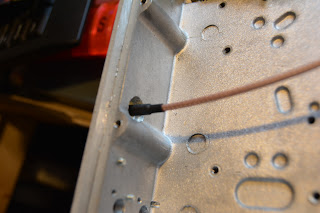
Now we need to lift a cap off the board and connect in where our RF feed will be:


Now for the bias for those lovely MOSFETS....  here's the board with my bodged bias circuit:


I reached out through the UK Microwavers Yahoo! group and have received some very useful information including this:


I've added an Arduino Nano into my enclosure and may have a bash at reading some of those control signals:


And throughout, Florrie the Ham cat has been assisting:


Next, a bit of testing.....

Local conditions.

Friday 10 March 2017

13cm Antennamabob

Well,

You may recall back here I installed a 13cm antenna on the mast, and here I built the 13cm VLNA from @DXING G4DDK. The VLNA is now mounted masthead with the associated switching and a separate feed for TX and RX as I described here:


I've also recently acquired myself a much wider frequency coverage Spectrum Analyser; it's a very old HP8593A which covers up to 22GHz and came from here and has nice things like a 2 year warranty:


So, using the Signal Generator I made back here, and a cheap Chinese directional coupler being used the "wrong way" round;


like this:


I can leave the Device Under Test port open circuit and see the amplitude of the signal from the sig gen on the Spec An. If I then connect the antenna to the DUT port and calculate the difference between the open signal and the signal with the antenna connected - that should be the return loss in dB:


So apologies for the really rubbish photo, but the higher peak is with the DUT open circuit - so a really pants SWR and the lower peak is with the antenna connected. That's a difference of about 30dB. So using the maths we established back here we can deduce that the SWR is about 1.07:1 - which is bang on the money.

I was rather hoping I could hear the Leicester beacon GB3LES on 2320.955MHz - but I can't. So there may be a number of reasons for that - including my poor N-Type connector soldering, so I will have to look further.

But progress none the less!

**UPDATE**

The Leicester beacon has a fixed antenna beaming 160 degrees from its location - that's almost completely in the wrong direction for me! I've tuned to the Telford beacon on 2320.870MHz and I can hear the beacon just fine - RX working!


Local conditions.

Wednesday 8 March 2017

6&4M Antenna and other Musings

Well,

I decided a while ago to remove the large 6/4M combined antenna I have - it's very big and heavy:


So, I decided a while ago to replace the 6/4M antenna with a 3 + 3 ele version that we originally bought for the UK ACs; this antenna had very little front to back so I wasn't happy with it for home. I've now decided to purchase the 4 + 4 ele version. All these antennas are from Innovantennas.

Now, I've bought quite a few antennas from them in my time - perhaps 10 or more. Every single one has had either no manual (sent by email normally), missing parts, the wrong parts or even one had the boom drilled incorrectly. This 4 + 4 ele is a bit better, it only had one broken pipe clamp. The instructions you receive from InnovAntennas are poor at best, but this example has to be the worst yet; take a look:


Now, there's something scribbled in the top right that looks like "ADD over Cap" - no idea what that means.

There's a box drawn on the 4M driven element and then scribbled out.

There's a box drawn on the 6M driven element with a scrawl that says "Plate oh tend Point" (I think this is plate at feed point) so we conclude that this was first scrawled on the 4M driven element and then crossed out.

Nothing to tell me which bolts to use where or anything resembling how to put it together.

Great antennas - rubbish quality control and instructions!

I've also continued the theme of 'scope obsession by making a circuit from W2AEW. This is a means of converting a composite video output (from say a camera) and displaying it on a 'scope screen by using the X, Y and Z inputs:


My build looks like this:


and it works a treat!

When Miss Luna Cat rolls on her back like this in front of Elmo Dog, this is interpreted, in human speak, as "thank God it's spring".


Local conditions.