Well,
I decided that there had to be an easy way to computer control my antenna rotators. I already have this on the Satellite antennas in Azimuth and Elevation, but not the "normal" antennas I have here for HF & VHF.
I looked on the big bad internet and found that Yaesu make a rotator interface for the G-1000 rotators that I have, but they are a simply staggering price.
So, there had to be a way....
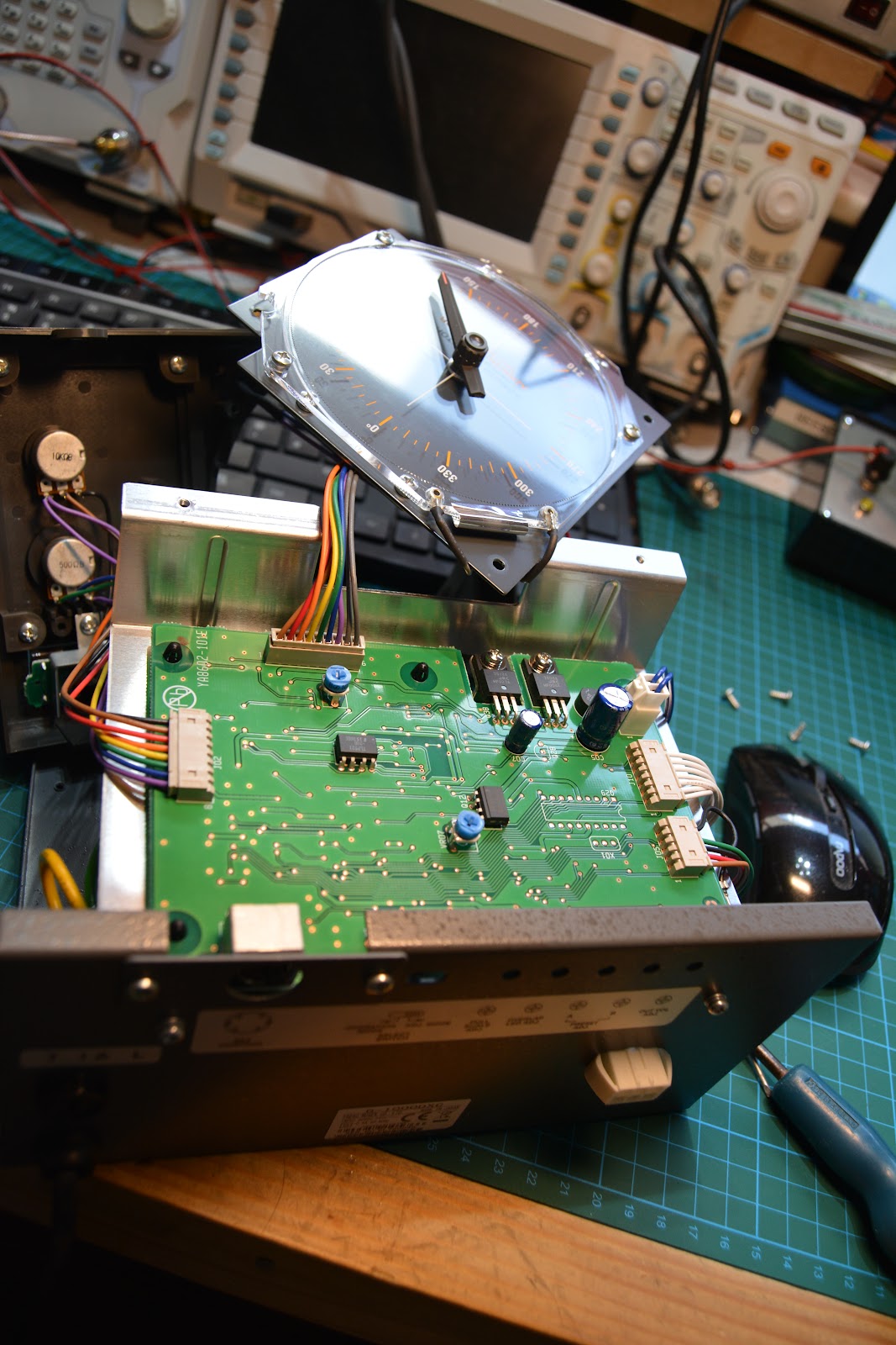
The first thing I did was connect to the interface socket on the back of the rotator and figure out which pin did what. We have a voltage output that represents the heading, which plotted like this:

Using simple bit of maths we can then create an equation to calculate the voltage at any heading (to save me having to keep moving the antennas back and forth):

There are also two pins on the interface connector that you ground to turn the rotor left and right. There's also a fourth pin you can use to set the rotator speed.
I then figured that Arduino was certainly the way to go, but then I found this:
https://blog.radioartisan.com/yaesu-rotator-computer-serial-interface/
Now, this interface does all I want and a million things more, it's been written in a way that allows you to configure the bits you want and exclude the bits you don't.
To get this to work with my G-1000 series rotator, I configured the following:
#define AZIMUTH_STARTING_POINT_DEFAULT 0
in the rotator_settings.h file; that's about it!
That setting defines the rotator as one that turns around 0 degrees (rather than 180 being the end stop).
Once I had done that and defined the pins (I just used the defaults) and also defined Digital pin 10 as the speed output:
#define azimuth_speed_voltage 10
in the rotator_pins.h file
I compiled the code for a Arduino Nano with an ATMega328 processor (because that is what I had lying around).
I then built the simple interface needed:

Now, the next step was to calibrate the software. Instead of turning the rotator from fully CCW to fully CW (including the 90 degree overlap), I just used the equation I established above to calculate the voltage and set the bench PSU to deliver same.

Then once that was complete, I connected the Arduino board to my Radio Control PC, fought with COM port settings (a favorite hobby of mine) and then configured my logging software to use a rotator controller emulating the Yaesu GS-232B command set.

So now I have this display above, it shows where the antennas are pointing and allows me to click on a heading to send the antennas there. I can also configure the system to auto turn the rotator based on selection of DX spot if I like too.
Neat, egh?
I decided that there had to be an easy way to computer control my antenna rotators. I already have this on the Satellite antennas in Azimuth and Elevation, but not the "normal" antennas I have here for HF & VHF.
I looked on the big bad internet and found that Yaesu make a rotator interface for the G-1000 rotators that I have, but they are a simply staggering price.
So, there had to be a way....
The first thing I did was connect to the interface socket on the back of the rotator and figure out which pin did what. We have a voltage output that represents the heading, which plotted like this:

Using simple bit of maths we can then create an equation to calculate the voltage at any heading (to save me having to keep moving the antennas back and forth):

There are also two pins on the interface connector that you ground to turn the rotor left and right. There's also a fourth pin you can use to set the rotator speed.
I then figured that Arduino was certainly the way to go, but then I found this:
https://blog.radioartisan.com/yaesu-rotator-computer-serial-interface/
Now, this interface does all I want and a million things more, it's been written in a way that allows you to configure the bits you want and exclude the bits you don't.
To get this to work with my G-1000 series rotator, I configured the following:
#define AZIMUTH_STARTING_POINT_DEFAULT 0
in the rotator_settings.h file; that's about it!
That setting defines the rotator as one that turns around 0 degrees (rather than 180 being the end stop).
Once I had done that and defined the pins (I just used the defaults) and also defined Digital pin 10 as the speed output:
#define azimuth_speed_voltage 10
in the rotator_pins.h file
I compiled the code for a Arduino Nano with an ATMega328 processor (because that is what I had lying around).
I then built the simple interface needed:

Now, the next step was to calibrate the software. Instead of turning the rotator from fully CCW to fully CW (including the 90 degree overlap), I just used the equation I established above to calculate the voltage and set the bench PSU to deliver same.

Then once that was complete, I connected the Arduino board to my Radio Control PC, fought with COM port settings (a favorite hobby of mine) and then configured my logging software to use a rotator controller emulating the Yaesu GS-232B command set.

So now I have this display above, it shows where the antennas are pointing and allows me to click on a heading to send the antennas there. I can also configure the system to auto turn the rotator based on selection of DX spot if I like too.
Neat, egh?