Search This Blog

Radio Guy Tees

Radio Guy Tees
Radio Guy T-Shirts

Sunday 28 August 2011

Resonant or Otherwise

As I suggested yesterday, today I have been trying to test a bunch of crystals to see if I can match their resonant frequency. I have set the DDS and 'scope up as the diagram below:


So because the crystal is in parallel with the DDS frequency generator, I have to tune the DDS to get the minimum reading on the scope; this will then be the resonant frequency of the crystal. I think I need to be cautious over introducing capacitance into the circuit through test leads to get an accurate frequency, but as all I am trying to do is match crystals, rather than accurately measure their resonant frequency, I figured it didn't matter that much as they were all tested under the same conditions.

I only have 10 10MHz crystals here, and these are the results I found:

So I have quite a difference between individual crystals. If I now add a Hi and Lo line to my graph, we can see that four crystals are actually quite close to each other:

So what I propose to do now is re-make my crystal filter from yesterday using crystal numbers 1, 2, 4 and 8 and then re-test to see if my bandwidth has improved.

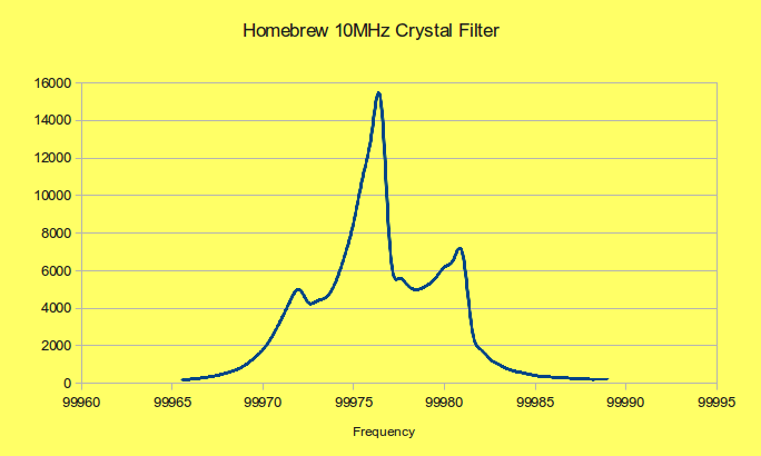
So after all that giggery pokery, the chart below shows the old crystal filter in red and the new one in blue:


So matching the crystals didn't make much difference, did it?

I can now calculate where the BFO in an SSB tranciever should be to get the USB and LSB passing through correctly:


So I'm going to go with these values and see how the performance looks.

Watch this space!

Saturday 27 August 2011

DDSing them Crystal Filters

I've been playing today with Crystal Filters. Firstly with one that I have made myself; this is an old design from the BITX and comprises 4 Crystals and 3 capacitors. What you would expect to find is that there is a bandwidth where RF isn't attenuated much around the design frequency and the rest of the RF spectrum shouldn't make it through the filter. There should be a slope either side of the design frequency where the attenuation increases more and more; we're looking for a kind of skirt. When generating single sideband RF signals, we want the sideband to be well within the crystal pass band and the carrier (whatever is left after the balanced mixer) and the opposite sideband need to be significantly attenuated by the filter.

Well, I used the DDS I was making recently and hooked that up to the input of my Crystal Filter then hooked the output into the scope and the spectrum analyser. Quite quickly I was able to plot a graph of the performance of the filter.


Now, the axis of this graph is in hundreds of KHz, so the bandwidth of this filter is extremely narrow, here's what it looked like on the spectrum analyser.


Now, once I'd seen this I decided to repeat the experiment with a commercial filter, this time the axis is incrementing in 2 tenths of a KHz, so the bandwidth, whilst a bit peaky is much, much wider than mine homebrew version.

I conclude that the bandwidth of my filter is way too narrow and I suspect this is due to badly (read not at all) matched crystals. I need to now hook up some method of measuring the resonance of individual crystals, but now that I have the made the DDS function and can use it as a very accurate signal generator this should not pose such a problem. So, tomorrow I will be matching crystals, remaking the filter and looking once more at the bandwidth and hoping for a rather different result.

I new that DDS would come in handy for something.

Good, egh?

Sunday 21 August 2011

DDS this and DDS that

Well,

Its long overdue but finally I have a week off; I'm even going to be home alone for some of the time so there is a real opportunity to play in the shack.

I spent the whole of yesterday trying to install a PIC programming environment onto my Linux PC; no success. When I found myself editing other peoples c code to try and make it compatible with the latest versos of make and automake I decided enough was enough. Disappointing but that's just the way it goes.

The reason for more PIC programming was because I bought myself a DDS development board from some bloke in China. I've been making a PIC based interface; I wanted to be able to use the PC to control the DDS settings via a simple interface; what I have ended up with is a PIC (16F628) running some software communicating with the PC hyperterm via RS232. This alows me to enter the various configurable DDS parameters and then the PIC software blasts the control words down to the DDS. Just a shame I've got it working in windows!

This is the veroboard constructed PIC & RS232 interface with the DDS board soldered to the side:

And this is the output; current the DDS is scanning from 1MHZ up to 60MHZ in a kind of test so the frequency here is quite low, it's very clean though:
So, this is now the start of a very stable VFO project for the transceiver I am slowly but surely building.

Good egh?

Here's the obligatory cat picture:


Saturday 6 August 2011

BITXing yet some more

Well,

I've been having some difficulties with the clarity of the signal out of my BITX 20 from ages ago:

http://g0mgx.blogspot.com/2010/12/bitxing-some-more.html

When I placed the unit back under test I found that the carrier suppression was as expected when the VFO was at the top of the band, but when it was elsewhere the carrier suppression was non existent. Now a quick look at the schematic will tell you that this simply isn't possible, however this video shows that it is:

Now, I've got the main board out of the box again and back under test on the bench:

Try as I may, I cant reproduce the problem when the unit is sat there. I have drawn the conclusion that I must have done something quite dumb in my wiring of the internals as the carrier suppression works just fine. The picture below shows the signal hooked from the top of the diode at Q11 on the BITX schematic. This is the LSB on the left, the supressed carrier in the middle and the USB on the RHS. The carrier to sideband bandwidth is 1.2 KHz because that is the frequency of the audio I'm injecting into the mic amplifier. It's worth noting that the spectrum analyser is a logarithmic instrument so this is showing the carrier at least 40dB below the sideband amplitude, given that 6dB is half the voltage, you wouldn't be able to see much of the carrier left on a scope at all!
Also the 14Mhz signal out of the exciter on this board looks clean enough on the scope and also on the spectrum analyser:
So tomorrow, I'm planning to re-do the internal wiring testing each stage as I go.

Damn cats haven't been helping much either:
Fun though, egh?