Search This Blog

Radio Guy Tees

Radio Guy Tees
Radio Guy T-Shirts

Monday 28 September 2015

Nearly Done - Starter for 10GHz

Well,

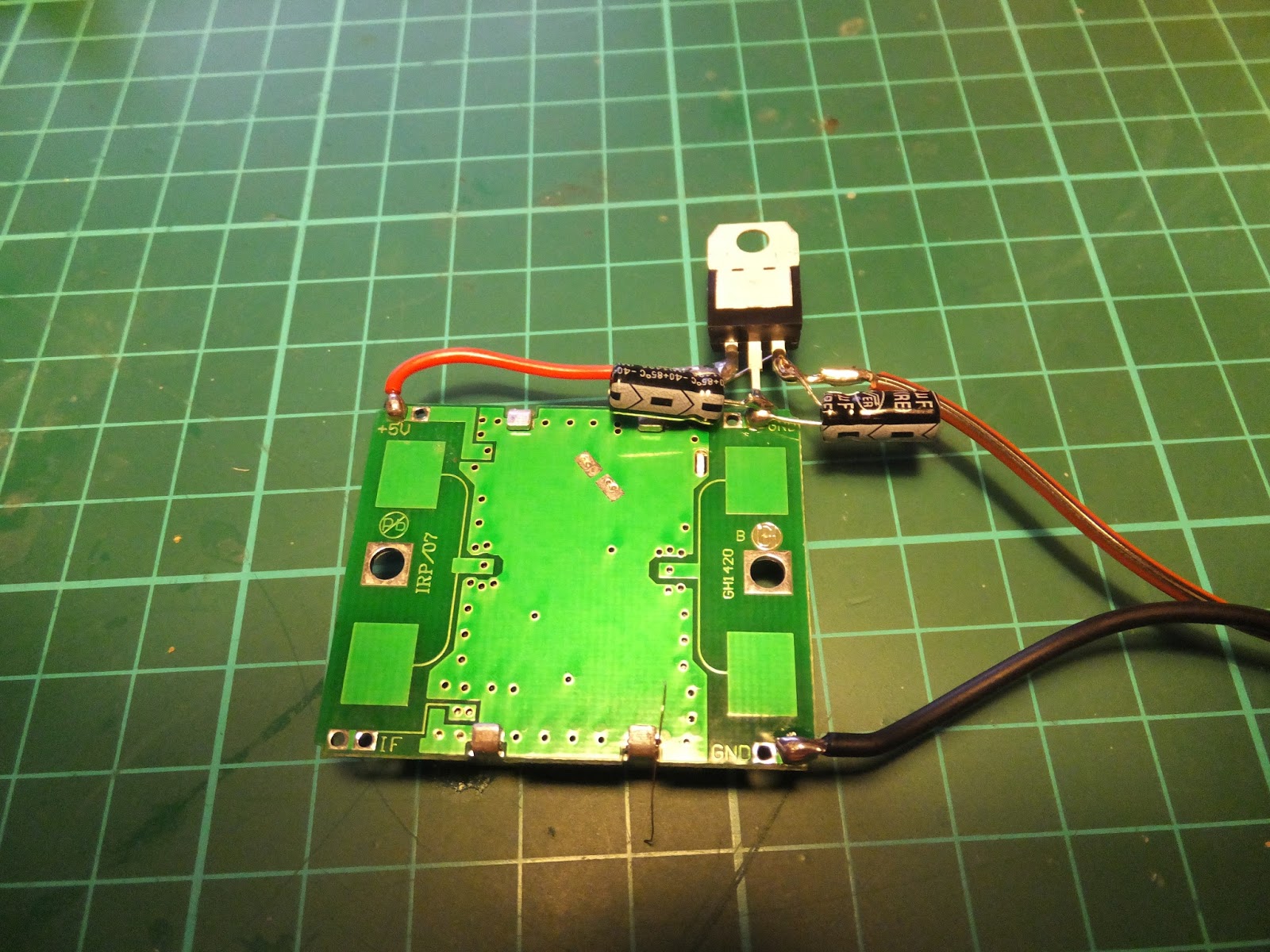
The final parts have fallen into place today. Firstly I have adjusted the HB100 from the ARRL $25 10GHz signal generator I mentioned last time to be as close to 10.368 GHz as possible using the LNB range extender for the Spectrum Analyser (also from last time).

The metal case contains a grub like screw underneath a QC sticker. Here you can see the device with the QC sticker removed. As luck would have it the trimmer for the coils in the transverters fits perfectly - you just turn the screw to adjust the frequency:


The other thing I have done is construct an interface box for the FT-817 to:
  • Putting the 3cm transverter into TX by sending DC up the IF coax;
  • Providing a AFSK digital mode interface from my laptop;
  • Giving a CW keyboard capability.
Here's the schematic:


Please note that the 'DC up the coax' bits are entirely stolen from here: http://www.g3pho.org.uk/

The actual device looks like this:


and it interfaces to the FT-817 through the two rear sockets for ACC and PKT.

So all in all I think I now have a CW, SSB and digital mode capability on 10 GHz.


Local conditions.

Sunday 27 September 2015

More Testing - Starter for 10GHz

Well,

You may recall a while ago I started a microwave project called "A Starter for 10GHz" and I did some basic testing of the RX here. Today I have been to visit Peter, G3PHO and his amazing emporium of test gear; together we have tested the TX side of the project successfully.

I've done a few other things since I came back from visiting Peter - the first being to devise a way to get my DC to 1.5GHz spectrum analyser to display 10GHz signals following some excellent inspiration from Peter.

Here's a picture of a eBay purchased LNB:


This device is very high specification and uses a PLL local oscillator, here's the spec (in German) from the box:


So basically it's designed to receive 10.7 GHz to 12.75GHz with a local oscillator of 9.75GHz. If you inject a tone to the DC supply you switch to the 10.6 GHz local oscillator also available, but we don't want that for our purpose.

Now, I've made a very simple Bias-T to send some DC up the coax feed to the LNB:


and used this to connect the LNB to the input of my Spectrum Analyser:
 

Very much inspired by the ARRL $25 10GHz Signal Generator I purchased a couple of the HB 100 units from eBay for a few $s. I have added a voltage regulator plus a couple of caps:


This is switched on and running on the bench as is BTThing I told you about back here. BTThing is set to 2592 MHz making the 4th harmonic at 10.368 GHz.

The Spectrum Analyser screen looks like this:


The smaller peak to the right is BTThing. Doing the maths, we have:

Which is pretty damn close to the 4th harmonic calculation of 10.368 GHz.

Using a similar technique:

We can deduce that the HB100 $25 ARRL signal generator is on 10.345 GHz.


Local conditions. All good egh?

Wednesday 16 September 2015

Windom Test - Shhhhh

Well,

Following the build of the Windom Antenna, I wanted to see if it was functioning, my primary band of interest was 80M. I left the TS-590 WSPRing on 80M last night and here is the result:


Looks like it works.

Local conditions.

Monday 14 September 2015

Baluns - Yet Again!

Well,

Part of the Windom I made last time here was a 4:1 balun. Now I tested one of those way back in time here. Back then I didn't much like what I saw as the frequency increased - it looked like the balun was only good to about 4MHz.

I came home with one of these the other day:


I bought in from LAM Communications in Barnsley.

Now, I repeated the tests I did way back when on this new balun and got more or less exactly what I expected. Here I am inputting a signal at 2MHz into the balun and looking at the two signals out. My expectation is that these two signals should be 180 degrees out of phase, as they are here:


The yellow and blue are the two outputs and the purple the difference between the two.

Now, as I increased frequency the last time I tested a balun this picture got very much "out of bonk" (a technical phrase meaning broken) with the phase difference between the signals moving significantly. On this balun all seems well at 25MHz and higher:


So - this balun seems to have good performance over the advertised range of frequencies - much better than the last one I tested!

As a consequence this is the balun installed on the new Windom.

Local conditions.

Saturday 12 September 2015

Another Windom, Really?

Well,

Having been thinking a little about my antennas I decided to take down the wire dipoles I have for 40M and 30M and try and squeeze in a full size Windom. It has fitted in the garden but the configuration is a little strange! It's kind of in a square where the feedpoint is in one of the corners.

Here's the dimensions of the antenna:


And here are the SWR readings I am getting in the shack starting at 80M:

40M:
30M:
20M:
17M:
15M:
12M:
10M:

So, all in all it looks quite promising! Time will tell as band conditions have been appalling over the past few days.

Here's a picture of our Elmo as he returned from the groomers yesterday - he was suitably unimpressed!


 Local conditions.