Some of you might remember my musings with the Red Pitaya back here; this was in the realms of SDR. I wanted to get myself a simple logic analyser and initially looked to that device to help.
Following on from my musings last time about this FeelTech Signal Generator I purchased from Amazon, I've created a video to demonstrate some of the issues I have been seeing.
There are quite a few of the issues captured in the video, but other ADDITIONAL issues I have seen but couldn't reproduce during the video are:
DC offset on Channel 1 (video demonstrates this issue on Channel 2 only)
Channel 1 and Channel 2 incorrectly out of phase
Both Channel 1 and Channel 2 failing to start (reproduced by both channels set to 10MHz and 0.5V then soft power cycle)
The issues documented in the video include:
Channel 2 fails to start on soft power cycle
Channel 1 and 2 amplitude issues
Issues around 0.5V amplitude
DC offset on Channel 2 (even during soft power off)
The firmware in my version is 3.2 which I understand to be the latest at the time of writing.
My conclusion? It's a piece of junk.
I'd be interested to learn if anyone else can reproduce these issues as it might be that this is some firmware but also I suspect crappy Chinese relays may be part of the problem.
My lovely Florrie Cat takes all credit for the production of the above video:
** UPDATE ** Since creating this post I have done a separate blog entry documenting the issues I have found with the unit here.
Following my recent musings on the FeelTech 3200 eBay sourced Function Generator here, I bought myself a model 6600 from Amazon.
Now, this one has a more fancy screen and has a spec claiming a 60MHz output on the sine wave function. The manual for the instrument clearly states that the outputs are 50 ohm, so I have connected the device to my 'scope using a 50 ohm transmission line and terminated it at 50 ohms.
My first observation is that the "Amplitude" setting on the generator has little or no resemblance to the output voltage measured into 50 ohms by the 'scope. The second observation is that there is some weird DC offset in the signal.
Here is the first example, 10 MHz signal at an amplitude setting of 2.0V (the manual says this is "default" peak to peak - I have found no way to change this "default" setting). For all these tests I have only adjusted the digit to the right of the decimal place, as highlighted in the image below:
and here is the resultant waveform:
So you can see in the 'scope image above that the signal is offset -ve DC.
Test 2, same frequency but amplitude now 1.4Vpp:
The signal is now 100% -ve. Test 3, 1Vpp:
Now, all -ve and some! Test 4, 0.6Vpp:
And then finally, at 0.5Vpp Amplitude setting there is a relay "clunk" inside the box and the DC offset becomes as expected:
I've managed to confuse the unit a few times by adjusting the amplitude several decimal places to the right of the point and then sometimes the amplitude seems to get stuck and doesn't change until you get to the 0.5V clunk point. I've also got the unit so that Channel 2 will produce no output - under both of these scenarios a mains power off then on fixes the issue.
The spectrum output of this 10 MHz signal seems quite clean:
And yes, the same poor PSU is in this device as the 3200. In this 6600 I've replaced the 2 prong mains input connector with one of a standard 3 pin variety and connected the earth line to 0V.
So what's that DC offset all about?
** UPDATE ** Since creating this post I have done a separate blog entry documenting the issues I have found with the unit here.
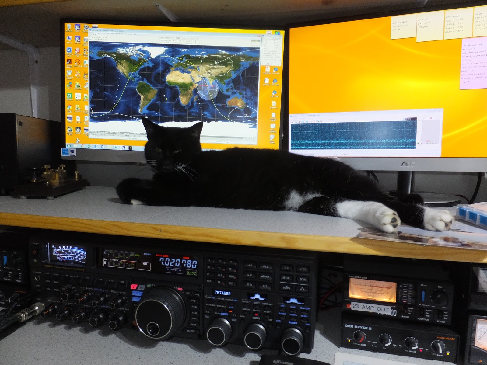
Here's Miss Luna Cat assisting with Satellite Tracking:
Following a discussion at a local radio club, I have been trying to put together a simple demonstration to illustrate standing waves on transmission lines. Now, this can be quite a complex topic, but here I will try and simplify the problem so we can see what's actually going on. There is a great explanation on Wiki here. W2AEW also has an excellent YouTube channel which covers some of this topic very well.
I am going to assume some prior knowledge about transmission lines, but here are the two basic questions that I often hear:
Why do I need to match my antenna to my coax and transmitter?
What is a good SWR and why does it matter?
Well, in the world of ham radio we match an antenna to a transmission line and a transmitter to minimise reflected waves, let's try and see why reflected waves are a bad thing.
My test setup here comprises a 50 ohm signal generator putting out a 10MHz square wave. We have a short length of 50 ohm coax to a BNC T-Piece and then another length of 50 ohm coax to a BNC connector.
The BNC connector on the end is connected to channel one of my scope (yellow waveforms) and the T-piece is connected to channel 2 of the scope (blue waveforms).
Now, with the 'scope set so that the end of the coax is seeing a 50 ohm load here are the signals that we see on the scope:
The signal at the end of the transmission line (yellow) is much the same as the signal part way along the transmission line (blue). We can even measure the delay from the t-piece part way along my transmission line to the end:
It is clear from the above scope screen that it has taken about 11ns for the signal to move from the T-Piece part way along my transmission line to the end.
Everything looks exactly as expected because the line is terminated at the design impedence of 50 ohms.
Now, if I change the line termination impedance to be 1M ohm, this is the scope screen now:
Here, two interesting things have happened. Firstly the amplitude of the signal at the end of the line (yellow) has doubled, secondly the signal at the T-piece part way alone the line is very distorted.
Because there is a mismatch (in this example a very bad mismatch), the change in impedance will generate a voltage spike which in turn will create a current flowing in the opposite direction, and that is exactly what we can see.
In the case of the yellow waveform, the signal ariving at the end of the transmission line has started to reflect 100% back down the line, but because we are "looking" right at the end of the line, there is no delay so the two signals simply sum together to double the waveform amplitude.
I've annotated the blue waveform to explain whats happening here:
So here we have at point A the start of the signal traveling from the signal generator to the load, 11 ns later (we measured the time earlier and can see its the same here) we reach point B, at this point the reflected waveform is arriving in the opposite direction on the transmission line and the two sum to make the total amplitude of the waveform. Point C is the end of the outgoing waveform and point D the end of the reflected waveform. This is why we see the two signals adding but slightly out of phase with each other - each step in the waveform is the 11ns we know it takes for the signal to travel from the t-piece in my transmission line to the end (or the same distance but in the other direction).
I can set up the scope to illustrate this kind of thing in another way, and the resultant view looks like this video here:
So in this video you need to imagine that the yellow waveform is travelling from left to right from the transmitter to the antenna. Similarly the blue waveform is the reflected waveform travelling from the antenna back to the transmitter. The purple waveform in the middle is the resultant signal on the transmission line - hopefully it's clear that this wave is "standing" and not moving - hence the name. The standing wave peaks at twice the amplitude of each of the individual signals because it is the sum of the two.
So in this mock-up example all the power from the transmitter is reaching the end of the transmission line and reflecting backwards to go back from whence it came - that's very bad for the RF source.
If we think about the calculation of SWR:
Hopefully, we can see that if the reflected power is the same as the forward power then the SWR is infinite.
If we take a second example whereby the forward waveform amplitude is 1 Vpp and the reflected 0.5 Vpp (50% of the forward voltage), then the forward power is 2.5 mW and the reflected 0.625 mW, then the maths tells us:
that the SWR is 3 : 1.
So before the SWR reaches a value considered "acceptable" we need to have a reflected power equal to 4% or less of the transmitted power as that will deliver an SWR of 1.5:1 or less.
I also hope you can see for the SWR to be 1:1 the reflected power needs to be zero and chasing this ultimate aim is rather pointless.
I've been fiddling a little this morning with my 2M VHF setup; I have been using my TS-990 with a G4DDK transverter along with a DG8 masthead preamp.
It works extremely well; I use this set of "macros" to put the TS-990 into transverter mode and set things the way I like them:
$COMMAND OM0D;$ Mode USB-D
$COMMAND FA00028370000;$ 28MHz VFO Frequency
$COMMAND FB00028375000;$ 28MHz VFO Frequency
$COMMAND XO000116000000;$ offset 116MHz +ve
$COMMAND XV1;$ transvert on
$COMMAND AN00911;$ DRV on and RX ANT On
$COMMAND PA00;$ main preamp off
$COMMAND PA10;$ sub preamp off
$COMMAND EQT00;$ TX Equaliser off
$COMMAND EQR000;$ RX Equaliser off
$COMMAND BS01;$ Scope on
$COMMAND PC200;$ Power control to 10 (70W in non transvert mode)
$COMMAND BSC020;$ Scope Ref -10dB
I bought myself a "FeelTech FY3200S" of eBay; this is a Chinese manufactured Arbitary Function Signal Generator/Counter that claims an output up to 24 MHz.
Now, the unit seems to work to spec and for the money it represents excellent value. The microprocessor and DDS board are good but there is a problem..... I can measure 97+V AC between the ground terminal of the output connectors and my mains earth - ouch!
This is because there is a very cheap SMPS inside with loads of leakage:
So, in the spirit of homebrew I have constructed a simple linear PSU:
I've gone to town a little on the heatsync, but you cant over do such a thing and the dissipation in the 5V regulator will be quite high. I am feeding the circuit above with a 1A rated 12-0-12 standard transformer:
As you can see there was loads of space in the case, I've mounted the three regulators on the heatsync and then attached that to the base of the case. The bolts securing the devices are countersunk on the underside of the lump of metal.
One thing I learned is that the 7912 -12V regulator seems to need a small load for it to regulate properly, hence I have added a 20mA drain on each rail in the form of an LED. More to add a small load than to provide an indication of function. I haven't located the LEDs on the front panel, they will stay buried inside the box.
Seems to work well:
I will probably now also add isolation between the USB port and the main board as currently when I connect my PC I am grounding the 0V lines of the generator; might be useful at some point to keep them floating and completely isolated from mains earth.