Search This Blog

Radio Guy Tees

Radio Guy Tees
Radio Guy T-Shirts

Sunday 30 October 2016

The SWR tripping issue

Well,

You may recall that back here I was starting to construct the SWR trip mechanism for the 23cm linear I built back here.  I've finished this and tested it today; as soon as the RF level on the reflected port reaches 10.8dBW my amplifier trips.

It looks like this in reality:


The return loss bridge is connected to the ANT socket of the linear and the forward and reflected ports are connected back to the amp box with SMA leads. Inside the box is the RF detector board that converts the RF into a -ve voltage and that has been adjusted in accordance with the calculations I did back here. So assuming the maths was correct I the linear will now trip if the SWR exceeds 1.8:1.

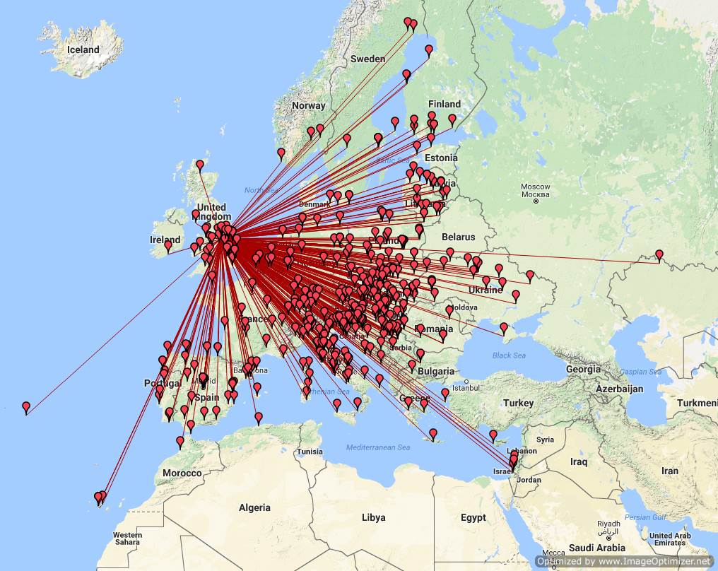
I also note there is good propagation on 2M today; looking out the window I see slightly misty but very still weather, often a sign on tropo:


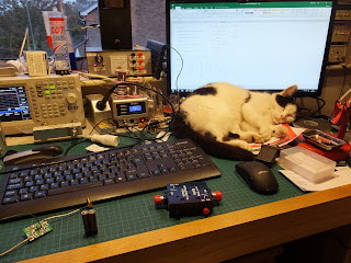
The situation with Chopsey (AKA Git Bastard Cat from Hell) using my desk as his bed is now completely out of hand:


Florrie the ham cat has also taken to sleeping terribly close to my nixie clock which I am very fearful for:


Local conditions.

Sunday 23 October 2016

Microwaves - now that's really nuts!

Well,

Following the build of my amplifier for 23cm here. I've been involved in some on-air tests of the JT modes on 23cm.

Here's a screen shot of my signels on JT65C as received by Tony, G4NBS in JO02af (Cambridge).


You will see multiple signals at times and we are sure this is due to Aircraft Scatter - I was seeing very much the same kind of thing on RX also. Anyhow, I am pleased to have logged 23cm JT65C QSOs with G4BAO. G4DDK and G4NBS.

I've been back up to Alport Heights in Derbyshire today with my 10GHz equipment from back here.


And have been listening to GB3FNY on 10,368.752 MHz:


I can find no trace of GB3LEX on 10,386.955 and can only assume it's off air.

Bonkers, egh?

Saturday 22 October 2016

Tripping over SWR

Well,

I've been thinking some more about the linear for 23cm I started back here, and more importantly how I can generate a high SWR trip signal for the control board.

I have one of these directional couplers:


It has a forward and reflected port at -30dB. Then I remembered I had one of these kits, which built looks like this:


This will turn the sampled RF into a -ve DC voltage for the SWR trip on the control board.

Now, fortunately or unfortunately we now need to do some maths to determine the attenuation needed. The RF detector board contains two samplers, I have configured one for the forward power and one for the reflected.

So, starting with the forward port:

Assuming a maximum output from the linear of 150W, we can convert that to dBW using:

So my 150W RF becomes 21.8 dBW. Therefore the maximum power at the forward port of the directional coupler is 21.8 - 30 = -8.24 dBW.

Given that the maximum input power to the detector part of the board needs to be 3mW or 0.003 W we can also calculate that 3mW = -25 dBW.

Therefore I need an attenuation of the difference which is roughly 16dB.

Then assuming a trip level of 1.8:1 (or about 10dB return loss) the reflected levels need to be 10dB down from the forward so an attenuator of 6dB is needed on the reflected port.

Using my signal generator at 1,000 MHz (1 GHz) and adjusting the output we find this is the response of the board:


So it all looks pretty good.

I now need to do some reading up on how I can drive the trip alarms on the control board, but this should do the trick nicely.

Here's the dogs doing what dogs do:


Local conditions.


Wednesday 19 October 2016

Wow - It's working then?

Well,

A couple of updates for you.

Firstly I ordered a 13cm 44 ele antenna, which duly arrived:

I suspect this one is designed for beaming round corner:

Not very clever!

Secondly, I was looking at my 6M logs recently and decided to create a map of my 6M contacts:


I just need that elusive USA opening!

Here's the 23cm amplifier I mentioned back here. It's finished now - I tried it on the air last night in the UKAC and received some good reports:


It's even wired quite neatly inside:


Cabinet feet and everything:

I'm really quite pleased with this. Local conditions.

Friday 14 October 2016

More 23cm Power Required!

Well,

The other night, there were a few of us trying out JT65C on 23cm. I could decode quite a few of the other stations but couldn't be heard. This is no surprise as I was using only 10W out of my IC-9100.

Quite a while ago I bought a 23cm PA module from PE1RKI - now this is a fairly serious bit of kit that I hadn't got round to doing anything with - until today.

I also bought a number of other items to go with the PA including a case, a switch mode PSU and a Ultimate Amplifier Control Board from W1PQL.

I built the control board and here it is just being attached to the rear panel of the amplifier case:


So the first thing in this kit board is a sequencer to handle all the different things we need to switch as part of going from TX ro RX and back again in a linear amp.

There's an ALC output -ve voltage to keep RF at nil from the driving radio, until such time as all the relays have gone clunk. Once that's happened the -ve voltage is removed and the RF allowed to flow.

Secondly there's a sequencer to drive the TX and RX co-ax relays plus turn on the main DC supply to the PA and it's bias. I have taken the advice from W1PQL and switched both the main DC supply and the bias off during RX. The main DC supply is switched by an external FET switch and the bias by an external relay as the current requirements of this amp are too high for the board to switch alone.

Here;s the SMPS I am using or the amp; it delivers 28V (it's a 24V unit with a pot adjustment) plus a separate 12V output. I can't remember the current rating but this amp needs 11 Amps at 28V so there should be more than enough here.


In the image below you can see the bulkhead N-Type connectors for the outside world, the control board, the external FET switch and the N-Type relay on the amp output. There's an SMA relay on the input which you can just see the side of on the far left of the picture. The second image shows the SMA relay much clearer.


Here's a close up of the innards of the amp itself:


Now, the control board would also control a fan based on a thermistor input - however I'm just wiring the fan on permanently in this build. It would also take a feed from a directional coupler and switch the amp off in the event of high SWR on the output - a most excellent idea - however, I don't have a directional coupler that will work at these frequencies so I guess we are going to risk it....


Chopsey AKA Bastard Cat from Hell hasn't helped much today:


Local conditions.

Tuesday 4 October 2016

It's all getting out of hand!

Well,

A weekend at the National Hamfest plus a trip to LAM Communications has resulted in two new radios.... One is new and one is very second hand....

I've had to make another shelving unit to accomodate... that really is it now.... no more!

Local conditions.