Well,
Following my changes to the 3cm and 13cm setup to become more portable, I decided it was only fitting to re-make the 23cm setup I made back here. I'll reuse the PA and the transverter.
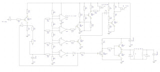
The first stage in this project will be to create a new sequencer, much like the 13cm version, so we can switch the transverter, a VLNA and a co-ax relay.
Here's the design:
and in reality, this looks like this once built on stripboard:
I've already got a G4DDK VLNA for 23cm assembled here, and coax relays aplenty. John, G4BAO is just tweeking my 23cm 60W PA and once I have all the bits, we can mount them in another waterproof enclosure the same as the 3cm and 13cm setups.
As part of the sequencer design, I finalised my latching relay driver circuit and have finished up with this, included in the sequencer diagram above:
So this is what I have so far:
You can see the SG Labs transverter, the sequencer from above, the VLNA and the TX/RX switching - just the PA to be added.
I've tested one of my attenuators to get an exact value at 1296.2 MHz using zero span on my Spectrum Analyser Tracking Generator as a signal generator and concluded a value of 29 dB (its rated as 30dB).
So then I used this in line to my XL Microwave power meter to measure the output:
And in CW with key down on the FT-817 and 5W output, that reads 6.1dBm so we then add the 29 dB for the atenuator and I get 35.1 dBm which is about 3.25 Watts out of the transverter. It's only supposed to output a nominal 2W and 2.5W max - so I'm not too sure whats going on here.
I've set up the transverter to work with full bananas out from the FT-817 whilst on DC power, and the LEDs that indicate input power levels and output SWR are both shining green:
Here's a crazy cat of mine en route to a portable operation:
#GHZbands
Following my changes to the 3cm and 13cm setup to become more portable, I decided it was only fitting to re-make the 23cm setup I made back here. I'll reuse the PA and the transverter.
The first stage in this project will be to create a new sequencer, much like the 13cm version, so we can switch the transverter, a VLNA and a co-ax relay.
Here's the design:
and in reality, this looks like this once built on stripboard:
I've already got a G4DDK VLNA for 23cm assembled here, and coax relays aplenty. John, G4BAO is just tweeking my 23cm 60W PA and once I have all the bits, we can mount them in another waterproof enclosure the same as the 3cm and 13cm setups.
As part of the sequencer design, I finalised my latching relay driver circuit and have finished up with this, included in the sequencer diagram above:
So this is what I have so far:
You can see the SG Labs transverter, the sequencer from above, the VLNA and the TX/RX switching - just the PA to be added.
I've tested one of my attenuators to get an exact value at 1296.2 MHz using zero span on my Spectrum Analyser Tracking Generator as a signal generator and concluded a value of 29 dB (its rated as 30dB).
So then I used this in line to my XL Microwave power meter to measure the output:
And in CW with key down on the FT-817 and 5W output, that reads 6.1dBm so we then add the 29 dB for the atenuator and I get 35.1 dBm which is about 3.25 Watts out of the transverter. It's only supposed to output a nominal 2W and 2.5W max - so I'm not too sure whats going on here.
I've set up the transverter to work with full bananas out from the FT-817 whilst on DC power, and the LEDs that indicate input power levels and output SWR are both shining green:
Here's a crazy cat of mine en route to a portable operation:


No comments:
Post a Comment