Search This Blog

Radio Guy Tees

Radio Guy Tees
Radio Guy T-Shirts
Showing posts with label RF sequencer. Show all posts

Saturday, 8 June 2019

More Sequencing Secrets

Well,

I've been making another sequencer with a bias-t included; it builds on the stuff I did back here. This time I ordered some kits from the very excellent W6PQL.

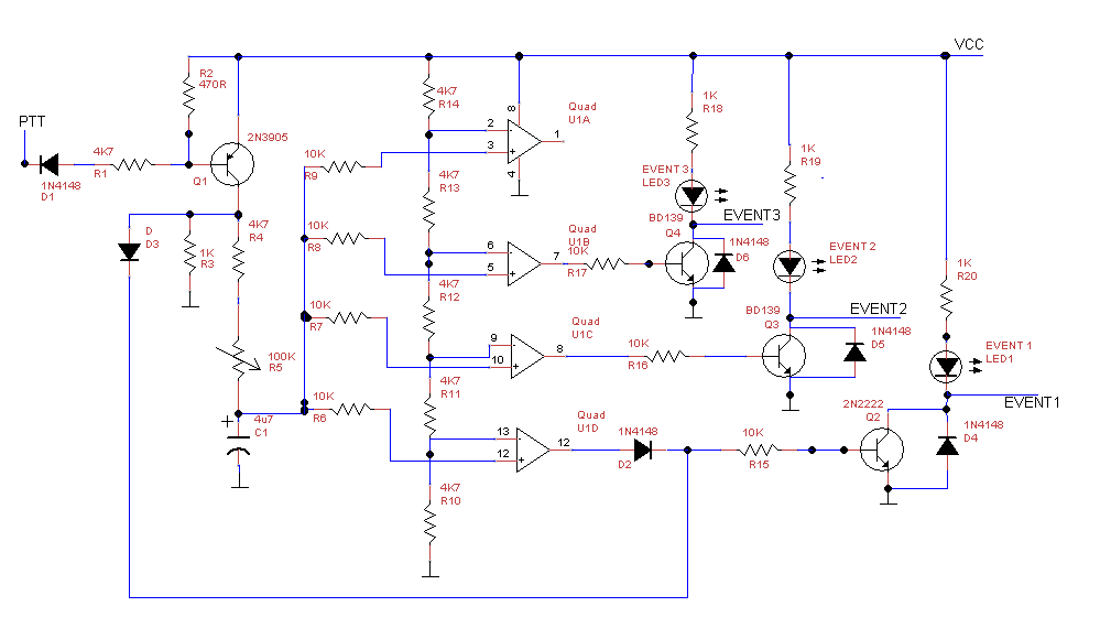
The basic schematic for the sequencer is this:


Here's the build:


You can see the sequencer, a FET switch (which is used to turn off the power to the Bias-T during TX) plus the bias-T itself.

The bias-T is the sequencer event 1, events 2, 3 and 4 are ground on TX and available on the back panel as RCA sockets.

I've added some LEDs to the front panel to show the events switching and also a control to adjust the delay timing of the sequencing. The case is recycled from an old project:


I plan to use this to control the Transverter(s) and other gubbins I mentioned related to EME last time at the bottom of the post.

Local conditions.

Tuesday, 27 December 2016

More Sequencing Secrets

Well,

I've added a FET switch to the sequencer I made last time. The FET switch will provide +12V on RX to the masthead and will be used to switch the masthead relay and also power the VLNA.

The schematic looks like this:


and it's built on the same bit of veroboard as the sequencer:


It switches very quickly, here in blue is the PTT being enabled and in Yellow the power supply that will head up the mast:


So we will then have 200+ ms delay before EVENT 1 from the sequencer:


which will be used for things like turning on the PA bias and enabling RF 'n' stuff like that.

All in all this is coming on nicely.

Local conditions.

Monday, 26 December 2016

Sequencing Secrets

Well,

I've been thinking some more about the 13cm project I have on the go, more importantly how I am going to arrange all the bits together.

Firstly we have a 13cm VLNA from G4DDK. I've started the build of this project - this is extreme soldering! the bits are very tiny indeed.

Here's where I am at with the project, unfortunately the last chip cap has made a bid for freedom and is in the carpet somewhere. Here partially built:


and here, almost complete all bar the input components:


Now, I also have the transverter from back here plus a ex telecoms PA that I will start to modify later.

I've started to draw the setup, to save on relays, switching and the associated losses, I will run separate feeds to the antenna (or masthead) for TX and RX. Also, due to the complexities associated with bias-T at these frequencies I will also feed power by cable.

I think it needs to look something like this:


So the thing labelled "gubbins" in the diagram above is actually a sequencer. Having built my 23cm amp back here utilised a ultimate amp control board from W6PQL, that included a sequencer and I had the schematic. So I drew this using non SMD components:


In reality it looks like this once built:


Looking at the top of C1 with a 'scope and grounding the D1 PTT line, we see this:


and as the voltage in C1 rises so the difference between the inverting and non-inverting inputs of the four op-amps swap in sequence as the voltage climbs to the power rail. Here you can see the output state change of the Event 1 op-amp in blue against C1 in yellow:


Event 2 happens later and then event 3 and 4. You can also see that they revert back in the opposite order as the voltage in D1 falls when the ground is removed from D1 and the capacitor discharges through D2 & D3.

Here's the timne delay from PTT to Event 1:


Those in the know tell me that these coax relays can bounce, so a delay of 200ms or more may be needed from thr relay power being initialised to any RF heading that way.


More to come!

Local conditions.