Search This Blog

Radio Guy Tees

Radio Guy Tees
Radio Guy T-Shirts
Showing posts with label DATV. Show all posts

Tuesday, 13 August 2019

Up-converting - you what?

Well,

Further to the PA I made last time, today I have been finishing off the up-converter to accompany it.

The theory goes something like this:


  • The Portsdown will output DATV on 439 MHz through the transverter output
  • This will be sent down the garden in Ecoflex-15
  • The co-ax losses will be compensated for using the 70cm amp I made back here
  • This will feed the SG Labs transverter we played with back here
  • The output of the transverter is then boosted by the Wi-Fi amp from here 
  • Finally the output is fed to the PA
Here's the up-converter in its finished form, there's a simple sequencer in there to handle the PTT switching and send a PTT signal to the PA:


Tomorrow I hope to install this and the PA in the small shed I have near the dish - then for some on-air testing.

This is the output of the up-converter DVB-S, SR250, FEC 1/2 - received with an antenna across the bench:


** UPDATE**

I've not yet installed the equipment in the garden, so I have about 4-5dB minimum of cable loss between the PA and the dish feed. However, here's my first RX of my own TV signal through Es-Hail'2:


** UPDATE 2 **

I've moved the gubbins to the small shed near the dish:


And am now sending 439MHz (ish) down the garden from the Portsdown.

This is a 333KS transmission via QO-100, you can see my signal on the left of the Mini Tioune software at 10,497.750 MHz:


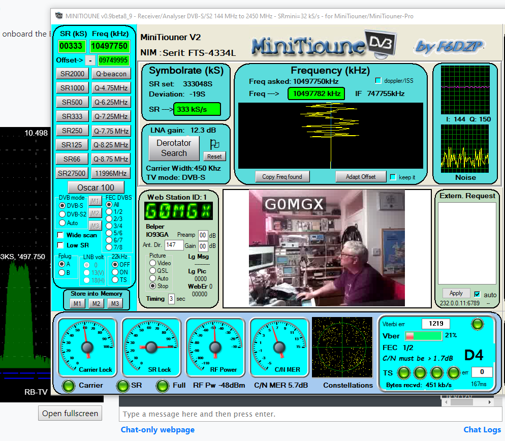
And here is a testcard:


Local conditions.

Sunday, 11 August 2019

Even More Power!

Well,

I've been messing about and finishing off my 13cm linear. The idea is to make something that will work on the 2.3GHz amateur band frequencies as well as 2.4GHz for DATV on Es'hail-2.

This has been quite a challenge, but eventually we have something working ready for on air testing.

This is the final build, which even though I say so myself, is a masterpiece:


The PA module itself is something from my travels made by PowerWave:


There are five MOSFETS in total - each one is a SRF7068H5HS.

This is controlled by a W6PQL Amplifier Control Board which in turn uses an external FET switch to turn on and off the 12V bias lines to the PA, provide the sequencing necessary, generate an ALC voltage (just in case I need it later), generate an external PTT out for switching VLNAs or other external gubbins.

There's also a chassis mounted directional coupler (a NARDA model 31152) which provides a -30dB forward and reflected port output which is attenuated and rectified to produce a DC voltage. There's a forward voltage for a future power meter and also a reflected power voltage to activate a trip if the SWR should exceed 2:1.


I've even included a thermistor on the main heatsync and a trip in the amp control to switch on the fans or even shutdown the amp when over temperature.

I'm seeing about 26dB of gain from the amplifier and it will generate about 250W of CW on 2.407 GHz so should easily generate the 30-40W I might need for some DATV experiments.

Here is the unit under test, I'm using the Portsdown to generate a signal at 432.75 MHz, then using the mixer from the UK Microwave Group forum to mix in 1975 MHz to generate an output on 2004.75 MHz. This is then amplified up and fed to the linear. The forward port of the directional coupler (-30dB) is coupled via another 20dB attenuator to my XL Microwave meter. A short piece of coathanger shoved into the front of the Spectrum Analyser allows me to measure the harmonics and also look at the TX waveform.


A thing of beauty is a joy to behold! I'm delighted with this.

Saturday, 20 April 2019

A Portsdown Conundrum

Well,

As part of my Es'hail-2 experiments, I am now preparing a DATV TX system for the satellite. I've ordered a Spectrian linear amplifier which seems to be the way to go, it looks like this but isnt here yet:


But in the mean time, I have been playing with an eBay sourced "wi-fi booster":


I have modified this to be permanently in TX by shorting pins of the op-amp as per many published explanations:


and simply connected this between the 23cm output port on the Portsdown and the Wi-Fi antenna that came with the amplifier.

Firstly, to test all is well with the setup, I have set the Portsdown to:


  • Frequency 146.5MHz
  • Modulation: DVB-S
  • Encoder: MPEG-2
  • Output to: Lime Mini
  • Source: TestCard
  • SR 1000
  • FEC 7/8
  • Lime Gain 88
This feeds from the 2M output port of the Portsdown to the linear I made back here and then to the 2M beam on the mast.

I have connected a "white stick" antenna thats on the house somewhere to the input of the MiniTiouner from here and these are the results:

Perfection!

Now, I change the Portsdown TX frequency to be 2407.75 MHz, change the antenna on the MiniTiouner to be a 2.4GHz patch on the bench:


and this is the result:

With a suitable piece of wire shoved into the front input socket on the spectrum analyser I can see the 2.4GHz signal I am transmitting:


So I am really not sure why I can't decode the TV signal on the MiniTiouner - any ideas anyone?


** UPDATE **

So, thanks to the BATC forum and mainly G8GKQ, we concluded this was a phase noise issue.

I did some experiments starting at 23cm (1296 MHz) and slowly increased the TX frequency until it failed; I found this to be at 2150 MHz. It turns out the problem is ripple in the PSU for the MiniTiouner - so this is an RX issue not a TX issue as I suspected.

The MiniTiouner includes a buck converter to take the DC input and drop it down to 4V to feed the on-board regulators. I was feeding this with either 12V or 18V and also routing this input voltage up the coax to the LNB. It seems that the higher the voltage, the more the ripple.

I've modified my MiniTiouner now to run the internal RX electronics from the USB power (I have it connected to a USB 3.0 PCI card with an internal PSU connection)  and only now use the external switchable 12/18V for the LNB power.

Not sure I fully understand the reason for the problem, but it is now fixed.

Local conditions.


Sunday, 24 February 2019

Portsdown - again?

Well,

I've been building myself another Portsdown DATV transmitter.

This is the Portsdown 2019 - instead of the Filter Modulator board in the last version, this uses a LimeSDR Mini.

I'm rather pleased with this new build, it's a lot neater than the 2018 version I made:


You can see the LimeSDR in the picture above, its in a 3D printed case - that's now got a 20mm square fan fitted.


The front panel is a lot better than the last build, if I had got the holes for the LEDs upright it would have been even better.


I wanted this second Portsdown so I can take it portable without destroying the shack to remove the 2018 version.

I'm rather pleased with this.


Thursday, 20 July 2017

First On-Air Test Complete

Well,

Thanks to the help of Col, G4OHV I have tonight tested my Portsdown transmitter on air.


Here's the video Col captured of my TX - Thanks!

Good, egh?

Saturday, 3 June 2017

Filters Filters Filters

Well,

Following on from the success of last time; it was time to make some filters around the 146.5 MHz DATV frequency on the NoV allocated bit of spectrum we have above the 2M band.

I've also built up a kit I have had here for a while, it's a PGA144 from G4DDK.


So at the top we have the PGA144, middle is the LPF and bottom is the BPF. The designs are really quite simple - just ask if you need the details. Here's the spectrum from all three:


The yellow is the PGA144 - it has a 20dB attenuator at the input so the signals are actually 20dB higher than shown - the gain at 145MHz is exactly 20dB.

The purple is the LPF being swept and looks just fine.

The Blue is my BPF which I am very pleased with - it looks great.

So next will be a 60W "brick" amplifier for 146.5 MHz - waiting for the bits but I have to go work in foreign parts for a week or two so will pick this up on my return.

Local conditions.

Wednesday, 31 May 2017

I think its working

Well,

Following from my musings last time on the BATC Portsdown project; I think mine is now up and running.

I've been working on a box for the project and the various bits and bobs are now inside:


So, following the suggested test setup I've configured the transmitter to TX on 1255 MHz using 2000KS (thats the symbol rate) and my newly invented DATV receiver from here sees this:


So I conclude it's working. Now to try and stream some video and then think about external amplifiers and filters!

I've decided to initially aim at 146.5Mhz in the NoV only allocation above 2M as my first target frequency.

I've set the Portsdown to tx on 146.5MHz, 7/8FEC with a symbol rate of 333KS. The output close up looks like this:


Checking on the harmonic content we see this:


So I made a LPF (needed!) and now the output looks like this:


In reality the LPF looks like this:


It is a standard 3 inductor design with 22pf at each "end" and 43pf in the middle two locations. The inductors are 3 turns open wound on a 6mm drill bit.

I've hooked up the BATC supplied EasyCap USB device to the Portsdown and I have coupled up my AntennaCam and we can see this on the MiniTiouner receiver we made here:


So, the next thing I need is a TestCard for TX; enter another great use of a Rasperry Pi. I've installed the software called TCANIM from here. I've followed the instructions to the letter but I cant seem to get a video signal out of the Pi AV socket....


Local conditions.

Tuesday, 30 May 2017

Portsdown where?

Well,

As part of the project I mentioned last time, I've started to construct the hardware for the BATC Portsdown project.

The fist board I have tackled has been the LO filter. This goes post the AD4135 LO which uses the same development board as we used on the 4.4 GHz signal generator.

This is extreme, extreme soldering! I've invested in a flux pen of decent quality from Farnell and that's made my life much easier. Previously I was using some cheap eBay sourced flux which was a load of dingos kidneys.

Here's the results of my days soldering:


There's basically a 2 bit input thats status determines which of the three on board filters are in line (or bypassed on 23cm). I've tested this and can see three filters, not too sure about their shape though.

4M:


2M:


70cm:


23cm:


Looks a bit odd to me, but lets see.

Local conditions.

Sunday, 28 May 2017

Telly - really?

Well,

I've started to play with Digital Television and the broadcasting thereof. The fist part of the puzzle was to construct a means of receiving my own signals so I chose the Minitiouner from the BATC of which I am a member.

I bought the PCBs and the bits and bobs from the BATC shop and have built the project:


The transmit side of things will be from the well publicised BATC project the Portsdown

There is quite a bit to this project, hardware wise, but initially we need a Raspberry Pi and some software to run something they call "Ugle Mode" whereby you can send a picture across the shack.

Well, it works:


So its time to progress the hardware some more and move forward with the transmitter side of the project.

Interesting start, egh?