Search This Blog

Radio Guy Tees

Radio Guy Tees
Radio Guy T-Shirts
Showing posts with label GPS disciplined frequency reference. Show all posts

Sunday, 10 May 2020

An experimental STM32 Frequency Counter

Well,

In an attempt to learn more about microcontroller programming I have done a little bit of training during this Covid-19 lockdown:


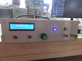
My first real attempt to use these skills is below. I've used a GPS 1pps signal to accurately count an external frequency. This is a GPS disciplined freuqnecy counter:


Good, isn't it?

Here is a picture of me (with Covid-19 dog clipper hair cut) and my beloved Bonnie dog:


Thursday, 30 April 2020

GPS Disciplined, again?

Well,

I've been trying to learn more about STM32 microcontrollers, their programming and to understand more about the on-board peripherals.

This is the result of my musings:


Fun, egh?

Sunday, 2 December 2018

Yet more Nixies!

Well,

My TEAS (Test Equipment Acquisition Syndrome) condition seems to worsen; I have acquired another Nixie frequency counter from that great auction site.

I've fiddled around with it considerably to get the internal clock to stabilise - some bright spark, maybe even the designer, has stuck a block of polystyrene (Styrofoam) over the crystal to try and maintain some temperature stability - but alas its all over the shop.

So, I've basically hacked two holes into the back of the unit and added an external reference clock input - this can be supplied by my ever faithful shack frequency reference.

So this is the unit; albeit on its side:


And here the small modification I've made:


The circuit forces whatever signal is on the input to be +ve DC - I've built it dead bug style on the back of the input BNC socket:


This is where I was poking about to find the clock output:


Using some of my other ancient test gear acquired through my TEAS condition:


Here's the result:


Lovely Jubbly.

Friday, 20 May 2016

Frequency Reference Completion

Well,

The project from last time is even in a box now:


Good egh?

You will see that we adhere to strict rules whereby the dogs are not allowed on the furnature:


Local conditions.

Tuesday, 17 May 2016

More Frequency Reference

So,

Following my musings last time over the QRP Labs GPS module, I've now also built two further kits from QRP Labs. The S5351A Module and the VFO.

When you combine all these together in the way I have you can create a GPS disciplined frequency reference with two outputs.

One of the outputs can be fixed in the firmware and I plan to put mine on 10MHz, I've made a low pass filter for this output to clean out the harmonics. The other output can be user set to any frequency up to about 290MHz or so.


Here's the LPF for the 10MHz output:


And here's the 10MHz output before the LPF:


and after:


All good, egh?

Sunday, 15 May 2016

Frequency Reference

Well,

Been thinking for a while that my shack frequency reference is a bit old hat and could be a bit more useful. What I would really like is a GPS disciplined VFO so I can set the frequency for my needs rather than only having 10MHz, 5MHz and 1MHz outputs as I do from the old project here:

http://g0mgx.blogspot.co.uk/2013/11/frequency-reference-how-accurate.html

So I have started to look at the possibility of using a newer device like the Si351A from Silicon Labs.

The first part of the project will be a new GPS receiver to give us the 1pps signal we need for the frequency control. I found a really neat kit at QRP Labs

I've built the kit today and it looks like this:


Mine has been built to utilise an external active GPS antenna.


The output from the 1pps looks like this on the 'scope:


So all seems well with the first phase.

More to follow!

Here's our Pepper Cat who has been almost completely in the way most of today:


Local conditions. Good egh?

Sunday, 17 November 2013

Man with two watches...

....never know correct time.

Because of this syndrome the correct thing for me to do now that I have established the GPS disciplined OCXO from here:

http://g0mgx.blogspot.co.uk/2013/11/gps-disciplined-really.html

Is to simply use this as the master frequency reference and calibrate everything else against it.

If I went ahead with my plan to use the GPS 1pps signal for a frequency counter, imagine the dilemma if they didn't agree! The GPS Disciplined OCXO uses some complex averaging to ensure that an out of sync 1pps pulse due to an aeroplane passing overhead or the washing machine (the second item isn't a likely cause; I am just checking you are paying attention) are not acted upon. Using the 1pps signal to gate a frequency counter wouldn't be able to do this.

So, to cut a long story short I have taken the frequency counter I first started here:

http://g0mgx.blogspot.co.uk/2011/07/pic-n-choose-how-to-count.html

And have calibrated it against the GPS OCXO:


So, all in all I am very pleased with the results of this project. I have learned a great deal and have a very accurate frequency reference and a counter to go with it. From conception to finish the counter project has only taken 2 years and 4 months!

Another great homebrewed addition to my RF workbench.

Good, egh?

Wednesday, 13 November 2013

Frequency Reference - How Accurate?

Well,

You may remember I mentioned a GPS disciplined Frequency Reference project that I found back here:

http://g0mgx.blogspot.co.uk/2013/11/the-art-of-calibration-once-more.html

I ordered and received the PCB for the project, here's the start of construction:


The main PCB connects to a OCXO which it alters the control voltage to adjust, and also connects to a GPS receiver.


Now, I started off with a GPS receiver that was advertised as being a timing and 1pps (pulse per second) output device. This is exactly what I need as the 1pps signal from the GPS timing is used to gate the counting of the signal from the OCXO and hence alter the frequency to be exact.

Anyhow, the GPS I bought, despite what it was advertised as being, didn't contain the 1pps firmware!


So I have another unit now, this one certainly does contain the 1pps gubbins, but I don't have the correct connector for the antenna feed! However, here's what the 1pps signal looks like:


As this is only about 3V +ve I suspect I will need to push this through a transistor switch, but whatever happens it looks good to me!

I've got 2 10MHz OCXOs here, and you can see them below on test:


The physically larger unit to the rear of the photo above has a variable adjustment between 0 and 8V, the one near the front is 0 - 2.54V. Also the one at the front seems to pull a huge amount of current while it is warming up its oven - like 2A.  That is going to present some difficulties; the rear unit only pulls about 500mA. So I'll probably go with the 8V adjust unit initially and see how it performs.

Cat's not impressed:


Fun though. egh?