Search This Blog

Radio Guy Tees

Radio Guy Tees
Radio Guy T-Shirts
Showing posts with label homebrew 70MHz RF source. Show all posts

Monday, 30 December 2013

Which one do you trust?

Well,

The linear that I started way back here:

http://g0mgx.blogspot.co.uk/2013/11/now-that-smoke-has-settled.html

is almost complete, I've done my best to calibrate the input power detection circuity and will certainly "trip" into an alarm state if I overdrive the amplifier brick. I have also calibrated a simple directional coupler on the output to give me both forward and reflected power indication.

I needed to understand the match that my antenna gives me on 4M, but the Antenna Analyser that I bought some months ago only goes as far as 50MHz and the other MFJ unit that I share with Vince, G0ORC seems to have a gap in the tuning at exactly the 70MHz band.

So, I used the return loss bridge from here:

http://g0mgx.blogspot.co.uk/2013/09/return-loss-bridge-where-does-it-lead.html

and explained how to use it for SWR measurement back here:

http://g0mgx.blogspot.co.uk/2013/10/so-lets-get-bit-smarter.html

So, hooking the antenna from here:

http://g0mgx.blogspot.co.uk/2013/05/thatll-never-work-will-it.html

we see this:


and focusing right on the 70MHz allocation only:


So, whilst it's not perfect, the antenna is a good match across the whole band. As the MS frequency it looks to be 1.3:1 - which is more than acceptable.

I need to introduce you to two new residents at G0MGX, they are Mother and Son, please meet Pepper and Freddie:


Fun, egh?

Thursday, 26 December 2013

Honestly? It's a mess!

Well,

I've been boxing the components for the 70MHz linear amplifier that I have been making:

http://g0mgx.blogspot.co.uk/2013/12/testing-times-for-my-linear-project.html

today. The control software is still very much under development, but in my usual build a bit, test a bit fashion, I need everything to be wired to the Arduino processor board now so I can make progress.

All in all, here's the list of separate bits I've ended up with:


  • Linear brick and heatsync
  • 48V SMPS Power Supply
  • 9-0-9 transformer for DC supplies
  • Fan for cooling
  • Veroboard containing the ancillary electronics for the Arduino relay and fan control plus the DC regulators for the +24, +12 and +9 rails
  • Low pass output filter
  • Arduino
  • LCD display
  • Directional coupler for output forward and reflected power reading
  • **huge** coax relay for the output switching
  • input attenuator
  • small coax relay for input switching
  • Current shunt
So all together there is a lot more than I bargained for!

Here's what it looks like today:


and I have to confess that this is one big mess that I hadn't set out to make. It should work OK, but the "junk box" style of part sourcing has resulted in some really bigger than needed bits....

Florrie cat's not been helping much today:

 
Progress, though, egh?

Saturday, 21 December 2013

More Mixing to 4M

Well,

Been fiddling some more in the shack today with the 70MHz linear amplifier that I am building. The first total screw up was that I need to make an input attenuator so I can drive with a 10W ish input signal and reduce it to about 2W to the amplifier module.

I used an on-line attenuator calculator to design the pad and purchased some suitably power rated components for the job. I soldered it together and then measured the attenuation with the Spectrum Analyser, here with a single fixed frequency output from the tracking generator:


Now, this looked very much like it was about a mile from my target value of attenuation of 7dB and I seen to have more like 20dB at 70MHz. This didn't make much sense.

So I stuck it on my return loss bridge I made back here:

http://g0mgx.blogspot.co.uk/2013/09/so-whats-happened-to-bridge-then.html

to see what the input match to 50R was. Here's what I saw:


Now, this is telling me that at 50R impedance the input SWR to my attenuator at 70MHz is 23:1 (ish) i.e. a complete load of dingos kidneys.

If I just connect a 20dB attenuator (much lower power rated) I made a while ago, I see this:


This one was only really built with HF In mind, but still the SWR at 70MHz is a respectable 1.2:1.

So - why is this attenuator I have made so pants? I now realise that the resistors I bought to make the attenuator are wire-wound rather than carbon. So we have buckets of inductance as well as resistance. That just won't do at all!

Whilst I was messing about with the attenuator I decided it would be a good idea to box the 70MHz TX converter I started to make here:

http://g0mgx.blogspot.co.uk/2012/07/mixing-better-than-before-70mhz.html

and then revisited recently here:

http://g0mgx.blogspot.co.uk/2013/12/testing-times-for-my-linear-project.html

Well, I made an output amplifier for it to raise the output level a bit and have boxed it with it's own PSU:


Clearly this should be built into a metal case but I only have this plastic one which will have to do. I must be aware of external RF when I am using it that may make the output wobble somewhat:


The output looks OK on the scope:


but if I were to use this as a TX converter and put the signal on-air I clearly need another low pass filter post the output amplifier I added as the harmonics are quite high:


So, another box for the shelf and a failed attenuator build.

You win some, you lose some.

Sunday, 15 December 2013

Testing Times for my Linear Project!

Well,

You may recall the 50/70MHz linear that I last reported on back here:

http://g0mgx.blogspot.co.uk/2013/12/70mhz-linear-progress-is-steady.html

The first thing I need to do is to test the main amplifier block to confirm all working as planned. Now, to do this I need a fairly accurate 70MHz signal to amplify - the problem is that the signal generator I made back here:

http://g0mgx.blogspot.co.uk/2013/10/so-hows-sig-gen.html

doesn't go that high.

Some of you may recall when I first started meddling with 70MHz that I made an experimental 70MHz transmit converter to take a 10MHz signal and mix it up to 70MHz back here:

http://g0mgx.blogspot.co.uk/2012/07/mixing-better-than-before-70mhz.html

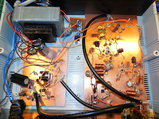
So I have dug that board out again, dusted it off and straightened a few bits that had got bent in the draw and stuck some power on it. I have the signal generator at 10MHz connected to the RF in port:


So in the picture above we have a 60MHz local oscillator and associated amp and filter along the top of the board, the connector on the RHS has the 10MHz signal from the signal generator then there is a diode doubly balanced mixer feeding another amp and output filter along the bottom. The output of this looks like this on the Spectrum Analyser:


And here on the 'scope:


It's important to understand that the Spectrum Analyser is a 50 ohm instrument - the 'scope isn't - hence the 'scope is terminated in a 50 ohm feed through you can see in the picture below:


So, using the data from the 'scope (which I suspect isn't too accurate at 70MHz) we can do some maths to calculate the power out of this concoction:


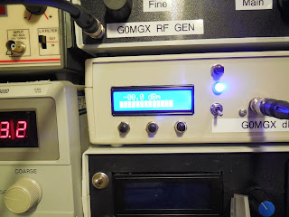
So, using the peak-to-peak voltage reading from the 'scope I get a power reading of about 1dBm. So, let's now connect the signal to the accurate power meter I built back here:

http://g0mgx.blogspot.co.uk/2012/11/the-art-of-calibration.html

And this is what I see (apart from a stupidly bright power light):


and if I set the reference level on the Spectrum Analyser to 10dBm this is what the signal looks like:


So it looks very much like a 0dBm signal at 70MHz to me.

All this test gear is really coming together- I trust the dBm meter I made very much - a great deal of effort went into calibrating it and there is no reason it should deviate from it's set up.

So now I need to hook up some power to the amplifier brick, terminate it through a power meter to a dummy load, throw the switch and see what happens.... watch this space.

Good, egh?