Search This Blog

Radio Guy Tees

Radio Guy Tees
Radio Guy T-Shirts

Saturday, 23 April 2011

WSPRing some more

How's about this then; this is WSPR running on 20M from my FT-950; with 10W of RF to a Windom suspended accross the back garden.

Not bad egh??

Friday, 22 April 2011

WSPRing with whispers

I've been playing with WSPR on HF for quite a while; it's a weak signal propagation reporter network. All you could ever want to know can be found here:

http://wsprnet.org/drupal/


I've successfully got 10W of RF received in all continents, but this screen shot was particularly impressive 1st thing this morning:

Not bad egh??

Monday, 18 April 2011

Bedini SSG Musings

I've been experimenting with a Bedini Simple Schoolgirl Monopole circuit; there's much more to follow, but to start with I've just posted some basic video of the machine running.

Here's the basic video:


Fun egh?

Saturday, 22 January 2011

Boxing the BITX

Sorry for the lack of postings, my job has been getting rather badly in the way of my homebrewing....

I've been getting some help cutting some of the not so round holes I needed for my BITX box. My friend Dean has done some of the metalwork for me (he is an Embroiderist by trade), combined with a photopaper front panel and the use of some fablon, I think the result is rather stunning!

I now need to create a scale for the s-meter, once that's done I'll begin adding the boards and other components to the inside....

Once it's all boxed and tested I'll be able to back to my linear project as I will be able to use this BITX as a suitable driver to test out the linear!

It's not bad though, egh?


Friday, 31 December 2010

BITXing Some More

I've just about finished the other bits and bobs for the BITX I was aligning yesterday. I've made a digital dial for the frequency readout and an s-meter; the readout is a kit I have had here for ages, it came from QRP Kits:

http://www.qrpkits.com

The build using surface mount components is really tricky, but it works OK second try!


1st time through I'd got some pins on the main microprocessor chip shorted out which was screwing up the multiplexing of the counter display. You really need to use a magnifying glass to see this stuff properly. Soldering it is another game again! I can't get the camera to take a picture any closer, so you'll just have to believe me when I say the components are small!

I've got all the bits of the BITX V3 wired together on the bench here (the mouse is not an essential part of the BITX):


Now, in a nutshell, what you should be able to see below is exactly what I love about ham radio, you can see the mess above which is all my own work, I turned it on, made a slight circuit modification (connected the speaker) and this is what I soon came across. There's only a piece of wire rammed in the antenna connector right now:


Not bad, egh????

Thursday, 30 December 2010

BITXing

A while ago I ordered a BITX20 V3 (Bi Directional Transceiver) from Sunil in India:

http://www.cqbitx.blogspot.com/

This is a 20M version of the ever popular QRP design of the BITX. There is a lot of information on the BITX design available, originally designed and built by Ashhar Farhan, 2004. The project details are here:

http://www.phonestack.com/farhan/bitx.html.

There is now a wealth of knowledge on the various forms of this original design available at a Yahoo! group here:

http://groups.yahoo.com/group/BITX20/

I was looking for a good drive for my linear amp project and figured I might as well build this project and use this to test the linear!

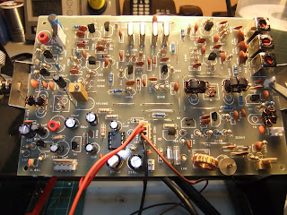
Some pictures of my build follow, generally this was very straightforward, although I have built a different version of this before:


Looking at the output of the PA with a constant drive from my audio generator, I've got about 70V pk-pk (the scope is connected using a x10 probe so it's 20V per division), that's about 8 watts. I would have expected a little better from a single IRF510 MOSFET. I used pk-pk voltage / 2 * .707 to give me RMS. Then squared the RMS and divided by 50 ohms.

So in this case I have 70 / 2 = 35V peak. Multiplied by 0.707 = 24.745V RMS

P = E^2 / R, so thats 20.745^2 = 430.355 / 50 Ohms = 8.607 watts.


The MOSFET is being powered from an unregulated supply of about 26.26V DC which is also being regulated down to 13.8V for the main board and the relays on the PSU/Linear board.

I'm now planning to build a s-meter, a frequency readout and then case this project. The output is looking really clean, so once these extra bits are complete I need to stick it on the air and get some reports!

This kit cost me $40 US plus some very modest shipping costs from India. The kit contains the boards, relays, a hard to find transistor, cables, connectors, torroids, enameled wire plus much more. If you are looking for a cheap and easy way onto 20M, it doesn't get much better than this! All other components needed for the build I had here in the shack already.

Friday, 24 December 2010

Balanced Modulator Musings

I've been fiddling further with the balanced modulator from the SSB exciter in my previous post to try and get some better carrier suppression. The first thing I have done is to match some IN5711's - these were the diodes used in the RadCom article I am copying. These diodes didn't make much difference, so I then decided to remove the balancing components from the circuit and re-wind the toriods. I originally used some FT50-43's as I had loads of these, but I have re-wound the toroids with FT37-43's and much tighter wound trifilar wire.

After all this I still didn't like the output much, so I then tried matching some good old IN4148's and still with no balancing components, and probably a more symmetrical layout:

This is now the output of the crystal filter on LSB:


And here on USB:


You can see that the carrier suppression is now very significant, so I think I am quite happy with this aspect of the exciter now.

The next part of this project will be to make the triple balanced modulator (TBM) as described in January 2011 RadCom. This will need five bifilar wound transformers on FT37-43's which I will need to have a good rummage to find! There is also some discussion on VHF transistors and the selection of the MPSA10 - which it just so happens I have about 100 of!

So onwards with this project over this coming holiday given suitable breaks from family commitments.

More soon.