Search This Blog

Radio Guy Tees

Radio Guy Tees
Radio Guy T-Shirts

Sunday, 19 January 2014

Yet more Minima!

Well,

Following on from yesterdays antics, I've done a little bit more this morning. Firstly I needed to make the "KISS" mixer I mentioned last time. It's a simple design using two FETs which are being switched on and off alternatively by the VFO signal. Here I have fed a 7MHz signal into the LPF which in turn feeds into the one RF port, the LO port has a 13MHz signal and the output is connected to the 50R terminated Spectrum Analyser:


So above we can see the large peak at 20MHz which is the sum of the two input signals - I adjusted the preset for the cleanest looking signal with the highest amplitude of the 20MHz sum output. Once we have the other parts of the transceiver built I can come back and fiddle with this some more.

Here we have a 7MHz signal into the LPF which in turn feeds into one RF port, the LO port has a 27MHz signal and the output is again connected to the SA:


I've tried to highlight some of the bigger peaks with markers in the image above; but I only have 4! There is the 7MHz signal and it's harmonics, the 27MHz LO signal plus all the sums, differences and other gubbins. In this example I am simply trying to see that the mixer is indeed mixing!

So here we have a 27MHz LO with a 20MHz signal to the RF port resulting in a 7MHz signal out of the 15MHz LPF:


Next to build is the crystal filter. This uses two parallel crystals at the input and output and a total of 8 matched 20MHz crystals are needed. I built a very simple test rig to enable individual crystals to be measured like this:


In this setup the frequency where the biggest attenuation takes place should be the exact resonant frequency of the crystal. You could just as easily do this with a manual signal generator and look for the smallest signal on a 'scope. Here's an example with a crystal in the test rig:


So I found a bag of 100 20MHz crystals and kept testing individuals until I found 8 that were very close to the marker frequency set in the image above. I then used these to create the crystal filter. Here's a sweep of the filter once built:


So this looks quite impressive, there's a very sharp skirt at each side - which we will need to suppress the carrier - we will have to adjust the USB and LSB BFO frequencies to get the required sideband within the filter and the carrier and the sideband we don't want attenuated.

Progress is fast and furious!

Saturday, 18 January 2014

Minima Filter Simulation

Well,

As my sweep of the 15MHz filter didn't look so clever, I've entered the design into QUCS:

This is the result of the simulation:


So that looks somewhat perfect! I need to check my build and also measure the inductors to check that my "theoretical" inductors (number of turns et cetera) actually measure correctly once wound.

So measuring the actual inductors I find I need about 1 turn less than theory on the T50-2 coils in the 15MHz filter. I have removed 1 turn from each and now my filter sweeps like this:


So it's better than it was but still far from perfect.

This is the inductors in the build now:


I will be very interested to learn what others end up with and if we can make a better match to the theory above!

Good, egh?

Minima - A Song by the Muppets?

Well,

Ashhar Farhan is well known in QRP radio circles for his creation of the BITX transceiver. It's a simplistic radio that uses bi-directional amplifier components. There must, by now, be hundreds built and also hundreds of variants on the air. I am in the process of constructing a 40M version here:

http://g0mgx.blogspot.co.uk/2014/01/gluing-some-old-bits-together-to-make.html

Now, there's a new design by Ashhar Farhan on the block - the Minima here:

http://www.phonestack.com/farhan/minima.html

this circuit and design looks really interesting, it's very simple but covers all HF bands with software (my favourite Arduino!) control and a Si570 as the local oscillator.

I just got a built one! Rummaging round the shack today and I a pretty sure I have all the bits here already - no purchase necessary!

So, I have made a start with the low pass filters. If you look at the schematic and accompanying text at the link above you will see there are two low pass filters, one that includes a notch at 20MHz.

So, here is the finished pair of filters at G0MGX:


the toroids and inductor design that I used is as follows:


Here is a sweep of the 15MHz cut off low pass filter:


So this may need re-visiting at some point as the slope starts sooner than 15MHz. Here is the 30MHz cut off low pass before I added the traps:


and here after the three traps were added:


and an initial tune of the traps to 20MHz using the 22p trimmers:


and close up (sweeping from 18 to 22 MHz):


So, all in all, not a bad start!

The next bit to build will be the "KISS Mixer" - this looks very interesting. It's discussed in some detail in this paper:

http://www.phonestack.com/farhan/mixermusings.pdf

So, we need to make one and see how it performs!

Fun, egh?

Wednesday, 15 January 2014

And even more.....

Well,

Following on from the basic DDS VFO I got going yesterday here:

http://g0mgx.blogspot.co.uk/2014/01/yet-more-ddsing.html

I've done a little bit more.

I started with the software package QUCS I mentioned back here:

http://g0mgx.blogspot.co.uk/2013/12/qucs-simulation-you-what.html

And entered the parameters for a 25MHz cut off low pass filter, the tool designed the filter for me and I edited it to enter real world component values:

I then simulated the filter and got this result:


So I made it, now, to get the inductors correct, I just use the mini ring core calculator and pick a known inductor, enter the inductance I want and it calculates the number of turns for me. As long as that isn't too few to be practical or too many to fit, I go with it:


And this is what it looks like built and attached to the output of my DDS:


The output now looks like this terminated in 50R at the 'scope:


and this is the view on the Spectrum Analyser:


So, all in all, looking much better than before. I even found the trimmer tool and tweaked the band pass filter I made from the designs on the G-QRP pages, it looks like this at the moment:


and here's the sweep of the filter:


Cat's not been helping much:


Good, though, egh?

Tuesday, 14 January 2014

Yet more DDSing

Well,

Following on from my post yesterday about the BITX40 start:

http://g0mgx.blogspot.co.uk/2014/01/gluing-some-old-bits-together-to-make.html

I've finished the code for the AD9850 DDS based VFO for the transceiver.

This is what's on the bench right now:


There's an LCD display showing the VFO (well 10MHz less the VFO) frequency, plus the step size. A rotary encoder is connected to adjust the frequency and the push switch on the encoder selects the step size from 1KHz, 100Hz, 10Hz and 1Hz:


The output of the DDS on the Spectrum Analyser contains some strange and unexpected peaks at 30, 32 and 40 MHz. I'll probably add a simple low pass filter after the DDS to get rid of them (I thought there was one already on the DDS board?!)


I've included a calibrate routine where you adjust a non-volatile data value to set a 10MHz output frequency to exactly on the button. To do this I first calibrated my PIC based frequency counter from here:

http://g0mgx.blogspot.co.uk/2013/11/counting-once-more.html

using the GPS disciplined OCXO from here:

http://g0mgx.blogspot.co.uk/2013/11/gps-disciplined-really.html

So I can be fairly sure the output is on frequency.

The code is here if anyone is interested:

http://www.qsl.net/g/g0mgx//files/_40M_Bitx_DDS.ino

Anyhow, all good though, egh?

Monday, 13 January 2014

Gluing some old bits together to make a BITX40

Well,

Been fiddling around in the shack this evening and decided to build myself a homebrew 40M SSB Tranciever.

I'm going to base the design on the BITX as this is well tried and tested; I built a 20M version back here:

http://g0mgx.blogspot.co.uk/2011/01/boxing-bitx.html

The main differences will be that the bandpass filter will need to be for 7MHz and the VFO will need to be up at 17MHz.

I've looked up the G-QRP site this evening as I remember there was a good set of designs for bandpass filters on there; they use the old KANK series of tin can coils - I happen to have a lot of them:

http://www.gqrp.com/technical1.htm

I knocked a 7MHz filter together and this is what I see if I sweep the filter from 0 to 50MHz:


Not quite spot on 7.1MHz but pretty damn close; a quick tweak of the coil formers will soon bring that to the exact frequency we are looking for.

I then thought I would create a DDS for the 17MHz VFO. I looked up the old software I wrote back here:

http://g0mgx.blogspot.co.uk/2012/02/dds-running-well.html

Modified it for the AD9850 as I have some of those £4 eBay modules here (It was written for the AD9851), the differences are that the clock frequency is different as there is no clock multiplier on the AD9850, and hence the last 8 bits of the instruction to the DDS will need to all be 0 - for the AD9851 in clock multiplier mode on the AD9851 you need a 1 and 7 zeros....

I threw it together with an Arduino Uno I have here:


I bought some Uno processors from eBay recently with the bootstrap already loaded; this means I can homebrew the processor board and wont have to put a genuine Arduino board in the project when it's finished.


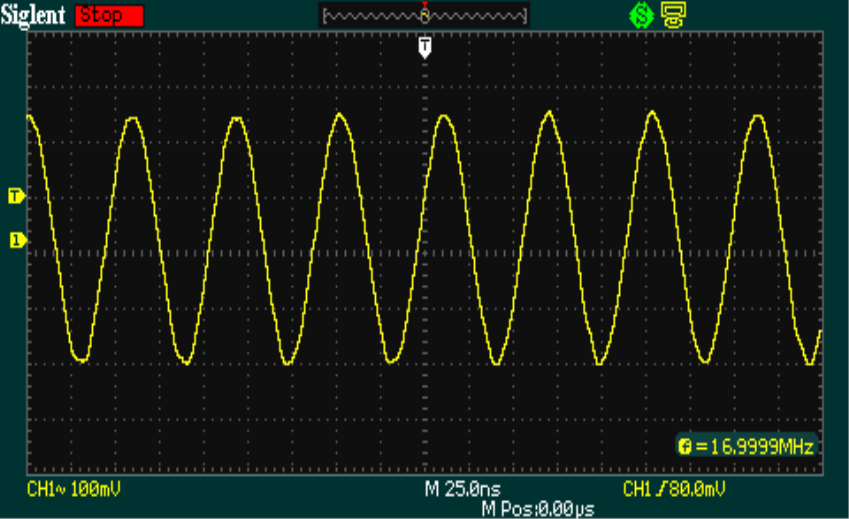
Anyhow, here's the output on the 'scope:


I just need to hook up a rotary encoder and re-use the VFO part of the DDS I created previously. A few mods to keep the frequency in the range I require, but that will be a piece of cake.

So, all in all, not a bad start, egh?

Sunday, 12 January 2014

Weighing scales? No, Meter Scales!

Well,

No after all the effort and learning that went into the 4M and 6M linear, I finally decided that I either needed to invest some money in all the correct bits to make one properly, or I needed to buy something. I ended up purchasing this:


The unit is currently propped up by an old computer and stuck on the floor - the amplifier seems to be a most excellent piece of equipment; I have had mine configured for 25W of drive and I am getting the expected levels of RF out on both 50MHz and 70MHz i.e. just over 300W.

I wanted to have a good power meter on the back end of the amplifier, but didn't want to make another one like my proper homebrew meter from here:

http://g0mgx.blogspot.co.uk/2012/11/scaling-heights-of-power.html

so I ended up creating a new scale for one of my mechanical meters I have. I haven't changed any of the internal workings jut made a scale with the numbers on that I wanted; n the high power range before you had to double the reading on the scale and the original scale was also very cluttered with a number of different number sets, here's the new one:


Its printed well and looks great in the meter. I am very pleased with the result - this has been created using software by Tonne Software:

http://tonnesoftware.com/

So all in all it's looking just great.

Good, egh?