Search This Blog

Radio Guy Tees

Radio Guy Tees
Radio Guy T-Shirts
Showing posts with label DDS. Show all posts

Wednesday, 13 August 2025

The Black ADF4351 Boards

 Well,

Some time ago, I did some expermimentation with black ADF4351 evaluation boards that are available at all good sites selling wares from the land where copyright means "lets copy it right".

I've bought some more recently and found that I couldn't get them to work.


Thanks to this post, I was able to deduce that the newer boards seem to be missing some bits - most importantly the CS line isn't tied high by a SMD resistor. Once I had pulled that pin high via 10K to the 3V3 line, the board worked as expected.

I've been using mine with a Pi Pico2:


You can see the additional 10K on the fritzing diagram above.

I have written some very simple code here to upload the register values to the device, and also have a spreadsheet here that will do the necessary maths from a target output frequency, channel spacing and clock frequency and generate the 6 register values needed to program the device.

Good stuff!


Saturday, 18 April 2020

A CW & WSPR Beacon

Well,

I've been fiddling some more with STM32 and have created a DDS based CW & WSPR beacon for 6M.

You can find the details of the project here:


The WSPR code is stolen from Anthony F4GOH, his code and other bits and bobs are on GitHub here:

https://github.com/f4goh/wspr

To counter any drift in the DDS, I've modified my AD9850 board to use an external signal for the clock and configured my Leo Bodnar GPS referenced oscilator to give me 10MHz from output 1 and 125MHz from output 2, thus:


The 125MHz is now used to drive the DDS. I'd be delighted to receive reports from the beacon, the CW signal is on 50.030 and every multiple of 10 mins it sends a 2 min WSPR transmission on 50.293 + 30Hz.

Here's the WSPR beacon RX from G0ORC:


No drift - not even a wobble! Excellent.

Fun, dont you think?

Tuesday, 14 January 2014

Yet more DDSing

Well,

Following on from my post yesterday about the BITX40 start:

http://g0mgx.blogspot.co.uk/2014/01/gluing-some-old-bits-together-to-make.html

I've finished the code for the AD9850 DDS based VFO for the transceiver.

This is what's on the bench right now:


There's an LCD display showing the VFO (well 10MHz less the VFO) frequency, plus the step size. A rotary encoder is connected to adjust the frequency and the push switch on the encoder selects the step size from 1KHz, 100Hz, 10Hz and 1Hz:


The output of the DDS on the Spectrum Analyser contains some strange and unexpected peaks at 30, 32 and 40 MHz. I'll probably add a simple low pass filter after the DDS to get rid of them (I thought there was one already on the DDS board?!)


I've included a calibrate routine where you adjust a non-volatile data value to set a 10MHz output frequency to exactly on the button. To do this I first calibrated my PIC based frequency counter from here:

http://g0mgx.blogspot.co.uk/2013/11/counting-once-more.html

using the GPS disciplined OCXO from here:

http://g0mgx.blogspot.co.uk/2013/11/gps-disciplined-really.html

So I can be fairly sure the output is on frequency.

The code is here if anyone is interested:

http://www.qsl.net/g/g0mgx//files/_40M_Bitx_DDS.ino

Anyhow, all good though, egh?

Monday, 13 January 2014

Gluing some old bits together to make a BITX40

Well,

Been fiddling around in the shack this evening and decided to build myself a homebrew 40M SSB Tranciever.

I'm going to base the design on the BITX as this is well tried and tested; I built a 20M version back here:

http://g0mgx.blogspot.co.uk/2011/01/boxing-bitx.html

The main differences will be that the bandpass filter will need to be for 7MHz and the VFO will need to be up at 17MHz.

I've looked up the G-QRP site this evening as I remember there was a good set of designs for bandpass filters on there; they use the old KANK series of tin can coils - I happen to have a lot of them:

http://www.gqrp.com/technical1.htm

I knocked a 7MHz filter together and this is what I see if I sweep the filter from 0 to 50MHz:


Not quite spot on 7.1MHz but pretty damn close; a quick tweak of the coil formers will soon bring that to the exact frequency we are looking for.

I then thought I would create a DDS for the 17MHz VFO. I looked up the old software I wrote back here:

http://g0mgx.blogspot.co.uk/2012/02/dds-running-well.html

Modified it for the AD9850 as I have some of those £4 eBay modules here (It was written for the AD9851), the differences are that the clock frequency is different as there is no clock multiplier on the AD9850, and hence the last 8 bits of the instruction to the DDS will need to all be 0 - for the AD9851 in clock multiplier mode on the AD9851 you need a 1 and 7 zeros....

I threw it together with an Arduino Uno I have here:


I bought some Uno processors from eBay recently with the bootstrap already loaded; this means I can homebrew the processor board and wont have to put a genuine Arduino board in the project when it's finished.


Anyhow, here's the output on the 'scope:


I just need to hook up a rotary encoder and re-use the VFO part of the DDS I created previously. A few mods to keep the frequency in the range I require, but that will be a piece of cake.

So, all in all, not a bad start, egh?

Friday, 21 December 2012

DDSing once more

Well,

I've been out of the country for a while; been working in the US of A. Great place, visited Chicago, Pittsburgh and Houston this trip - got myself some great boots!

Today I have broken up for Christmas and am looking forward to some good time at home with family, friends and, of course, my hobbies!

I've been fiddling today with the DDS signal generator I made here:

http://g0mgx.blogspot.co.uk/2012/02/dds-running-well.html

And would like to improve the design a little. It would be good to follow the DDS with a broadband RF amplifier, perhaps the one I used here would be a good starting point:

http://g0mgx.blogspot.co.uk/2012/06/its-been-ages.html

Who knows? I would also like to add a stepped output attenuator that's controlled by software and also feedback the RF output to one of the Analogue inputs of the Arduino so I can have a dbM display on the LCD, much like the separate meter I made recently:

http://g0mgx.blogspot.co.uk/2012/11/calibration-complete.html

So, my starting point was to replicate the existing project and then add the AD8307 logarithmic amplifier circuitry:


So here we are again, another project is born.

I'll keep you posted, fun though, egh?

Friday, 15 June 2012

It's been ages.....

Work, work and more work. That's all there is to it at the moment; finaly, however, I now have some time to:
  1. Catch up with my Blog;
  2. Play some Radio!
The WSPR and QRSS beacon I was begining to develop here:

http://g0mgx.blogspot.co.uk/2012/05/back-to-real-homebrewing.html

is finaly complete!

The output amplifier that I was fiddling with ended up as an Analogue Devices AD8008, which I ended up mounting on a kind of break out board that I had:


You can see how this helps with the "ugly" construction and the use of SMD devices. I can't remember where I got this break out type board from, but it certainly came in useful here!

Many, many moons ago I built myself an QRP ATU, and now I have it permanently hooked up between this beacon and a cheap vertical HF antenna I have slung up against the side of the house. So the setup looks like this:


The WSPR and QRSS beacon is written in C for Arduino:

www.arduino.cc

and I've made quite a few changes to the source code which can be found here in anyone is interested:

http://www.qsl.net/g0mgx/files/Mega_DDS_60_v2_1_G0MGX_eeprom.ino

I've got this hooked up to a GPS module which is sitting in the window of the shack, this is providing the timing data to the WSPR and QRSS beacon. Currently I've got it running on 30M and will be doing some checks for reports in the near future. It's utputting a stagering 20mW!!!!

I've also started (well nearly finided) re-writting the code for my recent DDS project in Arduino; I was never quite happy with the way that ended up, so using my new found C skills I have written (from scratch) the DDS control software.

The original project is here:

http://g0mgx.blogspot.co.uk/2012/02/dds-running-well.html

The functionality is the same as before, it's just that it works better and I have a much better understanding of how it works.

The source code for this is here:

http://www.qsl.net/g0mgx/files/G0MGX_DDS_FINAL.ino

I can claim some originality in this one!

Here's the inside of the replacement DDS, you can see that it's now Arduino based:


Please excuse the clothes pegs; they are just holding bits in place whilst the glue dries. I'll post again about this piece of work once completed. It's kind of soak testing right now as there is a calibration routine included to adjust the DDS for any misalignment in the frequency output due to clock inaccuracies.

All good though, egh?

Saturday, 19 May 2012

More WSPRing and QRSSing

Well,

After my last ramblings here:

http://g0mgx.blogspot.co.uk/2012/05/back-to-real-homebrewing.html

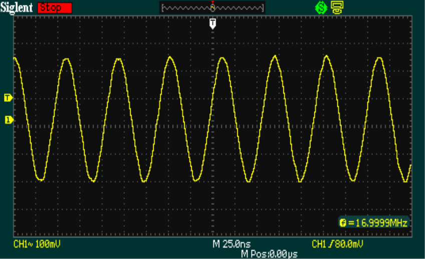
I've been doing some travelling with work, so progress is not so good. However, I have entered into a dialogue with a number of folk over my observation that the amplitude of the DSS reduces as the frequency increases. Some suggestions to overcome this mainly include AGC type circuitry or utilising pin 12 of the AD9851 to feedback a voltage to set the output amplitude based on a sample of the output (recursion see recursion). The most interesting feedback that I got, however, was not that the amplitude was dropping with an increase in frequency, but that my scope wasn't reading the signals correctly. The theory being that as the frequency increases my scope sensitivity drops off....

I ended up plotting this graph:


This is implying that my scope starts to take a dive, accuracy wise, after about 1MHz, this is the blue line with the y-axis indicating how many dB my scope is "deaf" by. The yellow line is the same signal but through the on-board low pass filter from the DDS module. This seems to imply that the LPF is rather badly designed also. If this theory is correct I need to subtract my scope deafness from the drop in signal out of the LPF. If at this stage we remember that 6dB is half voltage, this is not insignificant!

All rather confusing? My scope is a 100MHz rated fluke which I thought was supposed to be a good quality instrument. So, is this behaviour typical or is my scope a pile of dingos kidneys? I wonder...

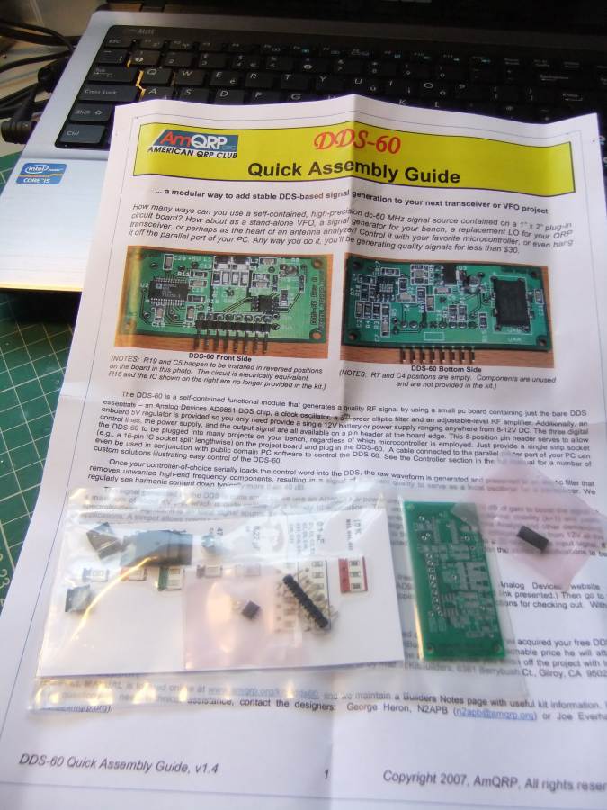
I've made a bit of progress boxing the WSPR and QRSS beacon project:


So far, I have tried a number of output amplifiers, the first based on the circuit in my original QRSS beacon, from back in December 2010:

http://g0mgx.blogspot.co.uk/2010/12/qrss-beacon.html

This gives me a nice clean 4v P-to-P voltage out, but I wanted more than that, so either I add another stage or do something else.


I have also tried an output amp based on the Analogue Devices AD8008, this works OK also. I'm off on my travels again tomorrow, so I'll pick this up again when I get back.

All good fun though, egh?

Monday, 7 May 2012

Back to real homebrewing!

You may recall my discovery back here:

http://g0mgx.blogspot.co.uk/2012/04/well-this-looks-just-great.html

So, Ive managed to make some progress. I've modified the software from W3PM from here:

http://www.knology.net/~gmarcus/

and have managed to get the GPS module working and also the DDS drive routines....


The code is written in C for the Arduino; and it's now interfaced to a four-line LCD, the AD9851 DDS module and the GPS receiver. The GPS module isn't in the picture as it's hanging out the window so it has visibility to the sky.


I've started to box the project, and have also built an RF amp to get me a staggering 100mW out...


Progress has been quite good today, I need to think about how I can get the RF levels the same on each band because as the frequency increases, so the amplitude out of the DDS and hence out of the RF amplifier decreases. I'm really not sure how to tackle that one, so I may have to ask for some help here.

Yesterday myself and Vince G0ORC went over to the "Dambusters Rally":


The rally was really good, albeit a bit small, but there was loads of really good radio junk to rummage about in. I picked up all sorts of stuff including this meter which I am rather proud of:


I've cleaned it up, mounted it on some wood, and stuck it in the corner of the shack with some amps flowing through it...


The next step will be to put some lighting inside...

Looks god though, agree?

Thursday, 12 April 2012

Extreme Soldering (DDS-60) Complete!

It seems that the extreme soldering is complete for another project! The DDS-60 I got from AmQRP is built.

I've found that photographing the soldering and then inspecting it blown up is about the best way I have found for checking the integrity of SMT soldering. Here is the complete board (top and bottom):


But when you actually look at the soldering blown up, it's quite a mess! I don't think there are actually any problems or shorts though:


Tomorrow or over the weekend I'll be testing this....

Fun, egh?

Wednesday, 11 April 2012

It's extreme soldering again!

Well, I've started with my Arduino WSPR beacon project from here:

http://g0mgx.blogspot.co.uk/2012/04/well-this-looks-just-great.html

I've hit some obstacles with the GPS module and am planning to come back to that bit later.

The original plan that I am going to follow uses an American QRP Club project the DDS-60.

http://midnightdesignsolutions.com/dds60/index.html

This is a AD9851 based DDS but includes a small on-board RF amplifier and a low pass 60MHz filter. As this was the board used in the design, I ordered one. It arrived today and looks like this:


It's another surface mount project and came very neatly packaged. I had to purchase the AD9851 separately (I think when the kit was originally put together you could get a sample from Analogue Devices). Now, this AD9851 is a very small component indeed and has 28 pins... Using a suitable soldering iron and a magnifying glass I have managed to get the chip on the board OK. This is the best I can manage to show the result:


If you open up the image above you can see that it's not a bad job. Here's the other SMD chip installed:


So the rest should be quite easy going in comparison as they are just Rs and Cs....

All in all not a bad start to the latest exercise in extreme soldering.. not bad, egh?

Thursday, 5 April 2012

GPS Time Sync? How's That Work Then?

I've made a bit of progress with the latest project that I mentioned here:

http://g0mgx.blogspot.co.uk/2012/04/well-this-looks-just-great.html

It's this project here for WSPering using the Arduino development board and the Analogue Devices DDS 9851 chip I've been experimenting with:

http://g0mgx.blogspot.co.uk/2012/02/its-even-in-box-now.html

So, I've got the Anduino board:


And have just soldered together the GPS module to get the timing information:


So I have no idea how to interface to this GPS module, but I have an extended Easter weekend to try and find out. There seem to be loads of reference pieces of code on the Internet for almost anything you could think of, so I'm sure I'll think of something.

Here's the Geddy cat, he really isn't helping much today:


Not such a great shot, but here's where the bed is (out of reach of the pesky Chopsy cat):
Fun, egh?

Sunday, 1 April 2012

Well, This Looks Just Great!!!!

Not much been happening here recently; the job is getting badly in the way.

Been WSPRing on 6m over the past few days; the results are rather dull but there are some interesting peaks in propagation across the UK.


I've been rummaging on the Internet and happened to stumble across this:

http://www.knology.net/~gmarcus/

This is a really neat project combining the Arduino technology (similar and a Cousin of Pinguino - well Pinguino is an off spring of Arduino) and the AD9851 DDS that I have been playing with recently.

I've just gotta build one!

So I've found the Arduino board in my local Maplin and the DDS boards I already have should work in this application so it's soon to be play time!

Here's the obligatory cat photo:

Watch this space!

Monday, 27 February 2012

It's Even in a Box Now!

Following on from my previous post; I've been busy boxing my DDS.


I bought a case from my local Maplin, it's the same case as my digital modes interface is boxed in from here:

http://g0mgx.blogspot.com/2011/10/how-come-its-siuch-damn-mess-again.html

I'm totally useless at cutting metal, so a plastic enclosure is the only real option if I want to do this myself, here is the front panel (with the display upside down) taking shape:


And placed into the outer frame:


Some clothes pegs hold it all together whilst the glue sets:


And here it is, finished:


Not bad, egh?

Sunday, 26 February 2012

DDS Running Well

Following on from my previous post I've been playing with the software for the DDS experiments I've been doing. The software is written in C and compiled in the Pinguino IDE and runs on the 4550 Pinguino board I made previously:

http://g0mgx.blogspot.com/2012/01/penguin-you-mean-penguino.html

Ed, EI9GQ, has been inspirational with this and other experiments of mine; his DDS VFO information can be found here:

http://homepage.eircom.net/~ei9gq/dds.html

I've posted a video on You Tube of the results of this recent experimentation here:


If anyone is interested, the source code for this DDS is here:

UPDATE 16/6/2012: I've re-written the code in Arduino (http://g0mgx.blogspot.co.uk/2012/06/its-been-ages.html):

http://www.qsl.net/g0mgx/files/G0MGX_DDS.ino

Fun, egh?

Wednesday, 22 February 2012

Progress is Fast and Furious!

After a bit of a false start with my latest DDS experiments, finally I have made a huge leap forward and made a pile of progress.

I was struggling to get the programming of this AD9851 to work successfully, but after resorting to reading the datasheet all became clear!

The AD9851 modeule is attached to my Pinguino board from my previous post:

http://g0mgx.blogspot.com/2012/01/so-hows-penguin.html

It's connected and setup in serial programming mode so there are actually only 3 connections plus ground between the DDS and the Pinguino PIC. 

The part I was struggling with was the on-board clocking of the AD9851. The older 9850 just runs and the clock speed you attach to it; however the 9851 has a 6X clock multiplier on-board. This small board has a 30MHz clock, so multiplied by 6 should be a clock speed of 180MHz; I wasn't seeing that. However, now I've cracked it and have it configured so that the clock is running at 180MHz.

So I've got the 4 line display running, I've got some test code that sets the DDS output at 5MHz and that's working fine. I know I can get the data entry keypad and the rotary encoder to work OK, so it's just the software now. I say just, hmmm, it may take me quite a while. But at least now I can write a bit of code and test it on this setup with confidence.

At last! It's so frustrating when you are playing with software and hardware - which do you blame. Nothing happening is rather hard to debug. At lest I now have a good solid starting point.

The only other thing I need to look into is the power supply to the AD9851. I've got it powered on the same +5V line as the PIC board, but it's running rather hot. But at least it's functional!

Pinguino rocks!