Search This Blog

Radio Guy Tees

Radio Guy Tees
Radio Guy T-Shirts
Showing posts with label 4-line LCD. Show all posts

Friday, 21 December 2012

DDSing once more

Well,

I've been out of the country for a while; been working in the US of A. Great place, visited Chicago, Pittsburgh and Houston this trip - got myself some great boots!

Today I have broken up for Christmas and am looking forward to some good time at home with family, friends and, of course, my hobbies!

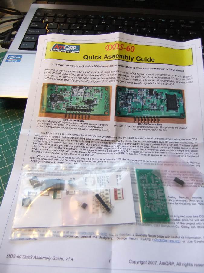
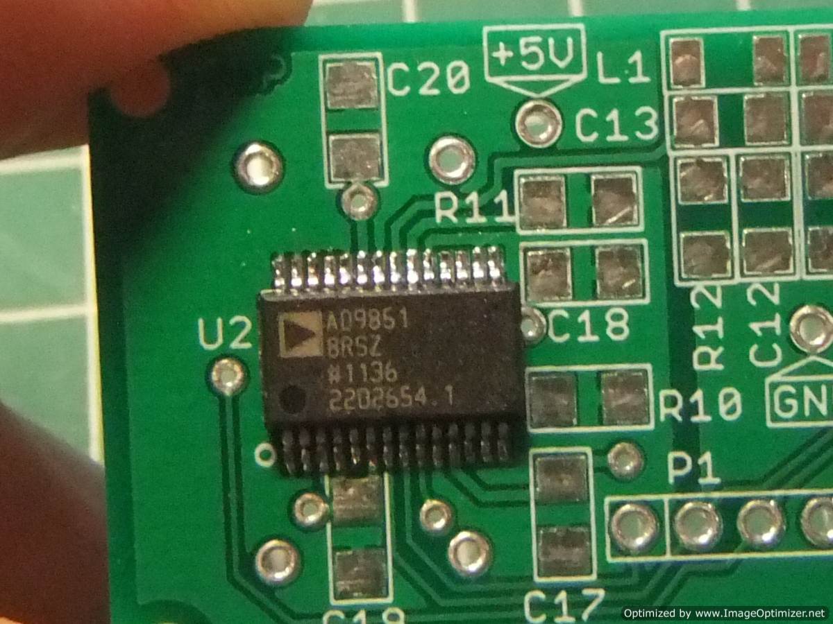
I've been fiddling today with the DDS signal generator I made here:

http://g0mgx.blogspot.co.uk/2012/02/dds-running-well.html

And would like to improve the design a little. It would be good to follow the DDS with a broadband RF amplifier, perhaps the one I used here would be a good starting point:

http://g0mgx.blogspot.co.uk/2012/06/its-been-ages.html

Who knows? I would also like to add a stepped output attenuator that's controlled by software and also feedback the RF output to one of the Analogue inputs of the Arduino so I can have a dbM display on the LCD, much like the separate meter I made recently:

http://g0mgx.blogspot.co.uk/2012/11/calibration-complete.html

So, my starting point was to replicate the existing project and then add the AD8307 logarithmic amplifier circuitry:


So here we are again, another project is born.

I'll keep you posted, fun though, egh?

Saturday, 3 November 2012

Scaling the heights of power

Well,

Having finally got a working digital and software based power meter, I have been running some experiments today - already this is proving to be a useful instrument. I think it might be worth making an alternative version of the system to be a stand alone power meter (rather than a directional meter with SWR calcs). However, the main enhancement today has been the inclusion of a (rather humorous) meter scale for the analog SWR meter:


All I did was remove the metal scale that came with the meter, scan it into the computer and then use MS Paint to alter it. I've printed it and stuck it to the old one with "pritt stick". Looks kind of fine to me:


The instrument display is looking pretty good too:


There are two switches on the front panel (as per the W7IEQ design). So I've modified the software to either sample the RF in a short mode or a longer, more time between samples mode. Hence you can see "Sht" for "Short" - this changes to "Lng" or "Long" when the 1st switch is set. Similarly I've added some code to peak hold the meter and this can be turned on with the second switch; the display shows "Norm" or "Hold".

I need to do something better with the front panel of the case and also I'd like to illuminate the meter.


Not bad though, egh?
 

Sunday, 28 October 2012

It's Becoming a Real Power Struggle

Well, blimey!

How hard can it be to get a piece of PIC assembler software to display some characters on an LCD display? The answer seems to be very.

I've started putting my power meter together, it's the one I started here:

http://g0mgx.blogspot.co.uk/2012/10/a-bit-of-power-struggle.html

Well, eventually I managed to assemble all the parts and put the boards into an enclosure I have here:


I've actually made quite a good job of the metalwork so far, I've intentionally not cut the hole for the display as I don't yet know which one of the many I have here I would end up using. Here's the view of the front panel as-is now, the meter looks OK but isn't the large meter I found, as that's just too big for the case!


So, PIC programmed, LCD display wired in, power on - nothing. Just some very faint black squares on the display that I can make more evident or go away using the on-board contrast control.

So, still not knowing if the software is intended to interface to an HD4470 compatible or not, the question was what to try next?

I ended up cutting the software back to just the display routines and simply programming the PIC with the code to display just a few characters on the LCD. Result - nothing.

So, next I added a simple loop at the end of the LCD routine calls to turn on and off one of the digital output ports every second. I attached a suitable LED to the port and tried again - as expected the LED started to flash. This told me a few things:

  • My PIC programming was working and my software was making it into the chip;
  • The software was reaching my loop for LED flashing so it wasn't getting stuck anywhere;
  • The routines for the LCD weren't working.
Now, you may (or may not) recall I did quite a bit of fiddling with LCD displays and Pinguino and more recently Arduino back here:

http://g0mgx.blogspot.co.uk/2012/02/four-isnt-quite-same-as-2.html

So from that messing about I had a reasonably good idea how the initialisation of these LCDs should look, and the code I was staring at didn't quite look the same. So I changed the sequence of numbers sent to the LCD to initialise it, re-programmed the PIC and tried again. Nothing.

Hmm, next I looked at the delays in the software between writing the Enable line on the LCD high and then low again - you kind of have to do an "open sesame" on the LCD every time you send it either data or a command and the delays in the assembly software I was looking at used the processor "nop" instruction. This is really a null operand and hence takes one (I think) clock tick to execute. I changed this to be a 1ms delay and.... Bingo! We have characters on the display:


So, my next puzzle was the fact that I could display the characters 0-9 OK, but any attempt at alpha characters resulted in, what looked very much like, Japanese characters appearing on the display. After much cursing, general muttering and many re-programming of the PIC to try different things, I found a short between two of the address lines on the board. Doh! It took me over 6 hours to find that as I was only looking in software....

So it does seem that I am moving in the correct direction. I have also found that the Assembly code I downloaded from the QST in-depth website for this project, doesn't assemble on my version of MPLAB. I've had to change a few things:

  • declared names are clearly case sensitive in my assembler and not used in that way in the code - many capitalisation changed;
  • literal values used with the "loadw" command - the decimal declarations used generated value too big warnings, all I have done is declare the values as the hex equivalent and prefixed with "0x" - I don't understand why this is different, but it assembles;
  • The declared names in the .inc file for the processor are also case sensitive so again, a number of changes needed there.
I then incorporated my changes to the display routines into the downloaded software and now I am seeing what I expected to see on the display.....

It's time to test the unit, I'll let you know how I get on. I suspect I need to re-make the directional coupler (again) as I posted a photo on the eHam.net homebrew forum and asked for some advice, here's a very polite post telling me what a pile of junk I have made:

eHam comments

Hard work, frustrating but all good though, egh?


Friday, 15 June 2012

It's been ages.....

Work, work and more work. That's all there is to it at the moment; finaly, however, I now have some time to:
  1. Catch up with my Blog;
  2. Play some Radio!
The WSPR and QRSS beacon I was begining to develop here:

http://g0mgx.blogspot.co.uk/2012/05/back-to-real-homebrewing.html

is finaly complete!

The output amplifier that I was fiddling with ended up as an Analogue Devices AD8008, which I ended up mounting on a kind of break out board that I had:


You can see how this helps with the "ugly" construction and the use of SMD devices. I can't remember where I got this break out type board from, but it certainly came in useful here!

Many, many moons ago I built myself an QRP ATU, and now I have it permanently hooked up between this beacon and a cheap vertical HF antenna I have slung up against the side of the house. So the setup looks like this:


The WSPR and QRSS beacon is written in C for Arduino:

www.arduino.cc

and I've made quite a few changes to the source code which can be found here in anyone is interested:

http://www.qsl.net/g0mgx/files/Mega_DDS_60_v2_1_G0MGX_eeprom.ino

I've got this hooked up to a GPS module which is sitting in the window of the shack, this is providing the timing data to the WSPR and QRSS beacon. Currently I've got it running on 30M and will be doing some checks for reports in the near future. It's utputting a stagering 20mW!!!!

I've also started (well nearly finided) re-writting the code for my recent DDS project in Arduino; I was never quite happy with the way that ended up, so using my new found C skills I have written (from scratch) the DDS control software.

The original project is here:

http://g0mgx.blogspot.co.uk/2012/02/dds-running-well.html

The functionality is the same as before, it's just that it works better and I have a much better understanding of how it works.

The source code for this is here:

http://www.qsl.net/g0mgx/files/G0MGX_DDS_FINAL.ino

I can claim some originality in this one!

Here's the inside of the replacement DDS, you can see that it's now Arduino based:


Please excuse the clothes pegs; they are just holding bits in place whilst the glue dries. I'll post again about this piece of work once completed. It's kind of soak testing right now as there is a calibration routine included to adjust the DDS for any misalignment in the frequency output due to clock inaccuracies.

All good though, egh?

Wednesday, 11 April 2012

It's extreme soldering again!

Well, I've started with my Arduino WSPR beacon project from here:

http://g0mgx.blogspot.co.uk/2012/04/well-this-looks-just-great.html

I've hit some obstacles with the GPS module and am planning to come back to that bit later.

The original plan that I am going to follow uses an American QRP Club project the DDS-60.

http://midnightdesignsolutions.com/dds60/index.html

This is a AD9851 based DDS but includes a small on-board RF amplifier and a low pass 60MHz filter. As this was the board used in the design, I ordered one. It arrived today and looks like this:


It's another surface mount project and came very neatly packaged. I had to purchase the AD9851 separately (I think when the kit was originally put together you could get a sample from Analogue Devices). Now, this AD9851 is a very small component indeed and has 28 pins... Using a suitable soldering iron and a magnifying glass I have managed to get the chip on the board OK. This is the best I can manage to show the result:


If you open up the image above you can see that it's not a bad job. Here's the other SMD chip installed:


So the rest should be quite easy going in comparison as they are just Rs and Cs....

All in all not a bad start to the latest exercise in extreme soldering.. not bad, egh?

Thursday, 5 April 2012

GPS Time Sync? How's That Work Then?

I've made a bit of progress with the latest project that I mentioned here:

http://g0mgx.blogspot.co.uk/2012/04/well-this-looks-just-great.html

It's this project here for WSPering using the Arduino development board and the Analogue Devices DDS 9851 chip I've been experimenting with:

http://g0mgx.blogspot.co.uk/2012/02/its-even-in-box-now.html

So, I've got the Anduino board:


And have just soldered together the GPS module to get the timing information:


So I have no idea how to interface to this GPS module, but I have an extended Easter weekend to try and find out. There seem to be loads of reference pieces of code on the Internet for almost anything you could think of, so I'm sure I'll think of something.

Here's the Geddy cat, he really isn't helping much today:


Not such a great shot, but here's where the bed is (out of reach of the pesky Chopsy cat):
Fun, egh?

Sunday, 26 February 2012

DDS Running Well

Following on from my previous post I've been playing with the software for the DDS experiments I've been doing. The software is written in C and compiled in the Pinguino IDE and runs on the 4550 Pinguino board I made previously:

http://g0mgx.blogspot.com/2012/01/penguin-you-mean-penguino.html

Ed, EI9GQ, has been inspirational with this and other experiments of mine; his DDS VFO information can be found here:

http://homepage.eircom.net/~ei9gq/dds.html

I've posted a video on You Tube of the results of this recent experimentation here:


If anyone is interested, the source code for this DDS is here:

UPDATE 16/6/2012: I've re-written the code in Arduino (http://g0mgx.blogspot.co.uk/2012/06/its-been-ages.html):

http://www.qsl.net/g0mgx/files/G0MGX_DDS.ino

Fun, egh?

Wednesday, 22 February 2012

Progress is Fast and Furious!

After a bit of a false start with my latest DDS experiments, finally I have made a huge leap forward and made a pile of progress.

I was struggling to get the programming of this AD9851 to work successfully, but after resorting to reading the datasheet all became clear!

The AD9851 modeule is attached to my Pinguino board from my previous post:

http://g0mgx.blogspot.com/2012/01/so-hows-penguin.html

It's connected and setup in serial programming mode so there are actually only 3 connections plus ground between the DDS and the Pinguino PIC. 

The part I was struggling with was the on-board clocking of the AD9851. The older 9850 just runs and the clock speed you attach to it; however the 9851 has a 6X clock multiplier on-board. This small board has a 30MHz clock, so multiplied by 6 should be a clock speed of 180MHz; I wasn't seeing that. However, now I've cracked it and have it configured so that the clock is running at 180MHz.

So I've got the 4 line display running, I've got some test code that sets the DDS output at 5MHz and that's working fine. I know I can get the data entry keypad and the rotary encoder to work OK, so it's just the software now. I say just, hmmm, it may take me quite a while. But at least now I can write a bit of code and test it on this setup with confidence.

At last! It's so frustrating when you are playing with software and hardware - which do you blame. Nothing happening is rather hard to debug. At lest I now have a good solid starting point.

The only other thing I need to look into is the power supply to the AD9851. I've got it powered on the same +5V line as the PIC board, but it's running rather hot. But at least it's functional!

Pinguino rocks!

Saturday, 11 February 2012

Four isn't quite the same as Two!

Firstly I have to report that my work is once again getting very badly in the way of my play time; there's not so much I can do about that if I want to continue to get paid. Therefore I shrug my solders and simply get on with it. Looks like I'm off to Abu Dhabi next weekend with my employer - I tend to travel a lot, but the United Arab Emirates for one day of work, even to me seems rather nuts.

So, in my last post I said that I wanted to use a 4-character display module for my latest DDS experiments; well this has kept me foxed for some time. It got so bad that I actually had to download the manufacturers data sheet and read it! Now that really is desperate!

I've got the display working now, it looks rather nice, but as usual is close to impossible to photograph:

But as you can see; I have successfully written to all four lines of the display. As it transpires this LCD module requires exactly the same initialisation as a 2 line module; the trick is in finding the address of the start of each line. They actually wrap so that line 1 feeds onto line 3 and line 2 and 4 proved just impossible to find!

I ended up with commands in hex of 80, C0, 94 and D4 for the start of lines 1, 2, 3 and 4 respectively. All of the code I'm developing to talk to this display is still using the Pinguino board and IDE I made back here:

http://g0mgx.blogspot.com/2012/01/penguin-you-mean-penguino.html

I'm still waiting for my Hong-Kong sourced AD8951 DDS chip, so the actual DDS experiments themselves will have to wait. At least I have some confidence that I can write to my display module of choice!

Cat's not been helping much as usual:


Good though, egh?

Sunday, 15 January 2012

So, how's the penguin?

I've been fiddling with my Pinguino board a little after the build I reported last time. I have, in fact, created a second board - this one will end up as my first Pinguino project. I would like to make a DDS signal generator, but this one needs to include a sweep function so I can more accurately measure crystal filters.

Here's the new board, you'll see that I have interfaced an LCD display, a keypad and if you look carefully you will see there is a rotary encoder there also:

The display has a really neat blue backlight, but is almost impossible to photograph:
I actually want to use a four line LCD display that I have here, I think the software needed to drive the four line display will be the same, I just wanted to start with something I am more familiar with. I am a great believer in build a bit - test a bit.

The keypad will be used for frequency entry, and I have that working OK - I wrote a test program to simply display the keypad entry on the LCD and that's working fine. The shaft encoder will be used to change the frequency steps by utilising the push click switch that's built into it and the rotary part will be tuning when in signal generation mode.

So far so good, but the DDS module I have here I used before:

http://g0mgx.blogspot.com/2011/08/dds-this-and-dds-that.html


This uses a AD9850 DDS chip, and at the time I was interested in the later AD9851 DDS but I couldn't find a way to buy the chip in anything other than the basic SMT package itself. A quick look on eBay suggests that you can now get development boards quite cheaply for this IC now so I have ordered one. It includes 6x clock multiplier on board so it should be easier to get extreme accuracy without spending a fortune on an accurate high stability high frequency clock module.

So, now I wait for a parcel from Hong Kong - why there aren't any in the UK I have no idea.

Time will tell, fun though, egh?