Search This Blog

Radio Guy Tees

Radio Guy Tees
Radio Guy T-Shirts
Showing posts with label Pinguino. Show all posts

Monday, 12 November 2012

My Power Struggle is Over

Well,

Following all the palaver associated with my Power Meter project; I've finally completed it.

Here's the finished article:


The front panel (which is covered in Fablon) isn't anything like as bumpy as it looks in the photo to the naked eye; it's perfectly acceptable.

I've finally decided that the switches need to switch between short and long sample times (as before) but the second switch that I had used to peak hold the meter, now switches the units primary display units from dbM to dbW - each of these has the power converted to watts in brackets.

The unit had quite a bit of use this weekend in the WAE RTTY contest - and yes I was sending and receiving QTC traffic! - but the meter certainly seems to work at full UK power from my linear, it's a damn site more accurate than anything else I have here, but most impressive was the ability of the unit to read really low reflected powers so I can tune the antenna far better with this unit than I can with any of the analogue meters I have here. This meter can tell be that I have -20dbW reflected power when an analogue meter wont even be moving.... I'm actually quite impressed.

Cat's not overly enthusiastic about it:

Impressive though, egh?


Friday, 2 November 2012

The Power is with me...

Well,

After all the antics with this power meter project, I've finally got a working project; however, not quite through the route you would imagine.

Having spent even more time studying the assembler code for the W7IEQ power meter, and realising that I would need to change all of the vast lookup tables used to convert the AtoD readings into dbM, I then found something in the code comments that made my heart nearly stop...

"This routine uses a packed 16-bit floating point value that I developed to reduce memory usage in a look-up table relating power in watts to measured ADC values for forward and reflected powers.

The packed values contain a 10-bit "reduced" mantissa (m) and a 6 bit shifted exponent (s).  All values are assumed positive so there is no need for a sign bit. Also, the first bit in the mantissa, which is always 1 except when the number id 0, is suppressed.  The offset value for the exponent is 27. A shifted exponent of 0 means the number is 0."

So I very rapidly concluded that I stood little or no chance of getting to grips with this in a hurry, and I was close to despair already with this anyhow!

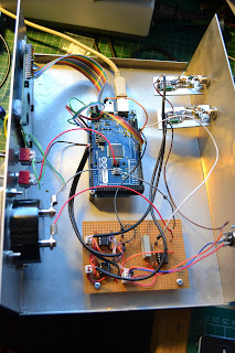
So, here's what I did.... Firstly I ripped the main board out of the box and threw it in the bin. Then I replicated the Sample and Hold op-amp circuitry plus the amp used to drive the meter on some veroboard. This board plus an Arduino

www.arduino.cc

board I had were introduced into the box....


So, I have the original AD8307 boards, but everything else has been replaced. I opened a blank arduino "sketch" (or project) and started from scratch to write the code....

Because the Arduino code is written in a high level language and there are very few memory or other limitations on the board itself, the code doesn't need to be especially well optimised for speed or size. Also the high level language and the library routines that come out of the box mean that all the "tricky" bits associated with reading the AtoD or setting the PWM et cetera are already available for use - so the software is really quite easy to write and also easy to read and modify by other people.

Here's a link to the code:

http://www.qsl.net/g/g0mgx//BlogFiles/power_meter.ino

and also the spreadsheet that I made to calibrate it:

http://www.qsl.net/g/g0mgx//BlogFiles/Power%20Meter%20Calibration%20Arduino.xlsx

So the LCD display is currently set up to display the forward and reflected power in Watts and dbM plus the calculated SWR. The SWR is also indicated on the meter.

The code took an evening to start and then about 6 hours to complete going with my ever favoured method of write a bit, test a bit.


There's lots left still to do, like a front panel and a meter scale. I will also introduce the concept of average power readings and things like that. But I think I need to see the unit in use before I can decide exactly how I want it to behave.

Cat's not impressed:

Good though, egh?

Monday, 27 February 2012

It's Even in a Box Now!

Following on from my previous post; I've been busy boxing my DDS.


I bought a case from my local Maplin, it's the same case as my digital modes interface is boxed in from here:

http://g0mgx.blogspot.com/2011/10/how-come-its-siuch-damn-mess-again.html

I'm totally useless at cutting metal, so a plastic enclosure is the only real option if I want to do this myself, here is the front panel (with the display upside down) taking shape:


And placed into the outer frame:


Some clothes pegs hold it all together whilst the glue sets:


And here it is, finished:


Not bad, egh?

Sunday, 26 February 2012

DDS Running Well

Following on from my previous post I've been playing with the software for the DDS experiments I've been doing. The software is written in C and compiled in the Pinguino IDE and runs on the 4550 Pinguino board I made previously:

http://g0mgx.blogspot.com/2012/01/penguin-you-mean-penguino.html

Ed, EI9GQ, has been inspirational with this and other experiments of mine; his DDS VFO information can be found here:

http://homepage.eircom.net/~ei9gq/dds.html

I've posted a video on You Tube of the results of this recent experimentation here:


If anyone is interested, the source code for this DDS is here:

UPDATE 16/6/2012: I've re-written the code in Arduino (http://g0mgx.blogspot.co.uk/2012/06/its-been-ages.html):

http://www.qsl.net/g0mgx/files/G0MGX_DDS.ino

Fun, egh?

Wednesday, 22 February 2012

Progress is Fast and Furious!

After a bit of a false start with my latest DDS experiments, finally I have made a huge leap forward and made a pile of progress.

I was struggling to get the programming of this AD9851 to work successfully, but after resorting to reading the datasheet all became clear!

The AD9851 modeule is attached to my Pinguino board from my previous post:

http://g0mgx.blogspot.com/2012/01/so-hows-penguin.html

It's connected and setup in serial programming mode so there are actually only 3 connections plus ground between the DDS and the Pinguino PIC. 

The part I was struggling with was the on-board clocking of the AD9851. The older 9850 just runs and the clock speed you attach to it; however the 9851 has a 6X clock multiplier on-board. This small board has a 30MHz clock, so multiplied by 6 should be a clock speed of 180MHz; I wasn't seeing that. However, now I've cracked it and have it configured so that the clock is running at 180MHz.

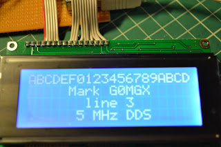
So I've got the 4 line display running, I've got some test code that sets the DDS output at 5MHz and that's working fine. I know I can get the data entry keypad and the rotary encoder to work OK, so it's just the software now. I say just, hmmm, it may take me quite a while. But at least now I can write a bit of code and test it on this setup with confidence.

At last! It's so frustrating when you are playing with software and hardware - which do you blame. Nothing happening is rather hard to debug. At lest I now have a good solid starting point.

The only other thing I need to look into is the power supply to the AD9851. I've got it powered on the same +5V line as the PIC board, but it's running rather hot. But at least it's functional!

Pinguino rocks!

Saturday, 11 February 2012

Four isn't quite the same as Two!

Firstly I have to report that my work is once again getting very badly in the way of my play time; there's not so much I can do about that if I want to continue to get paid. Therefore I shrug my solders and simply get on with it. Looks like I'm off to Abu Dhabi next weekend with my employer - I tend to travel a lot, but the United Arab Emirates for one day of work, even to me seems rather nuts.

So, in my last post I said that I wanted to use a 4-character display module for my latest DDS experiments; well this has kept me foxed for some time. It got so bad that I actually had to download the manufacturers data sheet and read it! Now that really is desperate!

I've got the display working now, it looks rather nice, but as usual is close to impossible to photograph:

But as you can see; I have successfully written to all four lines of the display. As it transpires this LCD module requires exactly the same initialisation as a 2 line module; the trick is in finding the address of the start of each line. They actually wrap so that line 1 feeds onto line 3 and line 2 and 4 proved just impossible to find!

I ended up with commands in hex of 80, C0, 94 and D4 for the start of lines 1, 2, 3 and 4 respectively. All of the code I'm developing to talk to this display is still using the Pinguino board and IDE I made back here:

http://g0mgx.blogspot.com/2012/01/penguin-you-mean-penguino.html

I'm still waiting for my Hong-Kong sourced AD8951 DDS chip, so the actual DDS experiments themselves will have to wait. At least I have some confidence that I can write to my display module of choice!

Cat's not been helping much as usual:


Good though, egh?

Sunday, 15 January 2012

So, how's the penguin?

I've been fiddling with my Pinguino board a little after the build I reported last time. I have, in fact, created a second board - this one will end up as my first Pinguino project. I would like to make a DDS signal generator, but this one needs to include a sweep function so I can more accurately measure crystal filters.

Here's the new board, you'll see that I have interfaced an LCD display, a keypad and if you look carefully you will see there is a rotary encoder there also:

The display has a really neat blue backlight, but is almost impossible to photograph:
I actually want to use a four line LCD display that I have here, I think the software needed to drive the four line display will be the same, I just wanted to start with something I am more familiar with. I am a great believer in build a bit - test a bit.

The keypad will be used for frequency entry, and I have that working OK - I wrote a test program to simply display the keypad entry on the LCD and that's working fine. The shaft encoder will be used to change the frequency steps by utilising the push click switch that's built into it and the rotary part will be tuning when in signal generation mode.

So far so good, but the DDS module I have here I used before:

http://g0mgx.blogspot.com/2011/08/dds-this-and-dds-that.html


This uses a AD9850 DDS chip, and at the time I was interested in the later AD9851 DDS but I couldn't find a way to buy the chip in anything other than the basic SMT package itself. A quick look on eBay suggests that you can now get development boards quite cheaply for this IC now so I have ordered one. It includes 6x clock multiplier on board so it should be easier to get extreme accuracy without spending a fortune on an accurate high stability high frequency clock module.

So, now I wait for a parcel from Hong Kong - why there aren't any in the UK I have no idea.

Time will tell, fun though, egh?

Monday, 9 January 2012

Penguin - you mean Pinguino!

Well,

For a few days I've been playing once again with Pinguino:

http://www.pinguino.cc/

It's an IDE that simplifies programming of PICs and the one I've built uses the 18F4550 PIC from Microchip. The board I have built is detailed here:

http://wiki.pinguino.cc/index.php/PIC18F4550_Pinguino

and it looks like this:


I had quite a bit of difficulty getting the IDE to run on Windows 7; previously I managed to get it running on Linux, but with some help from the Pinguino forum users, I was pointed at this tutorial:


Which has worked out just fine. The IDE is now running:


and this communicates with the board via a Bootloader that you have to program into the PIC. I accomplished this using my recent ebay purchased Olimex PIC board:

This board is directly compatible with the Microchip MPASM IDE and programming the PIC was a doddle.

Once the PIC was programmed and on-board my homebrew Pinguino I have managed to successfully download and run an initial test program to flash an LED. Not much to show for it, but good progress!

I'm planning to play some more with DDS and some other homebrew ideas I have; all of which will be PIC based.

Watch this space!