Search This Blog

Radio Guy Tees

Radio Guy Tees
Radio Guy T-Shirts
Showing posts with label Microchip. Show all posts

Wednesday, 2 January 2013

Calibration Finaly Complete (Really)

Well,

You may remember the musings from a while ago where I made the dBm meter for the shack:

http://g0mgx.blogspot.co.uk/2012/11/calibration-complete.html

I wasn't overly convinced of my calibration, the 'scope, spectrum analyser and this meter didn't align, especially at low power levels. There is always a risk that the old test equipment I have (the spectrum analyser) is well out of calibration, but I was curious. The calibrator that I made (Design courtesy of Mr Kopski, K3NHI) didn't quite look correct on the 'scope either - it was described as a square wave, but mine looked kind of triangular like this:


But it did look full of harmonics when viewed on the spectrum analyser:


So, I started by asking some suitably dumb questions on a forum or two, and ended up in a very educational and excellent email exchange with my new found chum Kerry who lives down under.

To cut a long story short, Kerry has some very accurate test kit (accurate read expensive!) and has kindly fed some known signals into an AD8307 RF front end (like the one in my power meter) and noted the voltage output by the device itself, here are the values:


So, I took these values and plotted them as a X-Y scatter plot in good old Excel, then added a trend line to each set of data and got the spreadsheet to include the equation on the graph:


Now, hopefully you will be able to see that using the equation on the graph, we can now calculate any dBm value that the meter should be displaying from the actual voltage on the device output (pin 4).

So, using my good faithful Avo signal generator and some of the attenuators I made earlier, plus the attenuator on the Avo itself, I have fed a load of different RF signals into the meter, read the voltage on pin 4 of the AD8307 and then used the equation to calculate the dBm value that the voltage represents:


Once this was complete (ignore the yellow above for now), I then used the lowest and nearest to 0dBm to calibrate the meter. The yellow values are the meter actual display readings once the calibration was complete.

My confidence is now very high in this homebrew instrument and I suspect it may become the most useful device yet.

So, feeding a -30dBm signal (as measured with the calibrated meter) into my Spectrum Analyser with the reference level (top line on the display) set to 0dBm, the fundamental 5MHz signal in this photo is shown -30dBm down from the 0dBm reference level i.e. they agree! Sorry about the wonky photo:


Here is the dBm meter with the Avo signal generator set at 0dBm and a -10dB attenuator (pad) in line with the feeder; 0.3dBm is really very close indeed:


Oh, and the suspect Kopski calibrator? That now reads 19.9dBm - can't be bad! It was the -50dBm version that I concocted myself that was highly suspect - it reads -39dBm!

I've started an Analogue equivalent of the meter, initially because this would only require a single calibration point, but now I have found a better way to calibrate the digital meter, the project is rather redundant. I'm rather pleased with the meter scale though:


And all this because I became suspicious of the readings I was seeing from the attenuators I created as part of this project:

http://g0mgx.blogspot.co.uk/2012/12/ddsing-once-more.html

Hey, Ho. Perhaps now I am happy with the dBm meter, I can progress that project? Unfortunately I've run out of holiday and have to go back to work. I suppose there's always next Christmas.

Fun though, egh?

Saturday, 17 November 2012

The Art of Calibration

Well,

Been thinking some more about power meters and the calibration of them. Quite tricky really, as you need an known RF source to calibrate a meter against it, but to have an accurate and known RF source, you need a calibrated meter to measure it. Recursion: see recursion.

The first thing I have done is to build a power meter that was published in QST, it's designed by Roger Hayward, KA7EXM and is PIC based. This is a stand alone meter for simply measuring from about -80dBm to +7dBm:


Then to calibrate this baby the text says... "assume for a moment that you have an accurate signal generator capable of -70dBm to +7dBm"..... well I don't!

So, a newly found homebrew chum in VK land pointed me at an article by Bob Kopski, K3NHI where he presents a simple calibration source using a CMOS clock oscillator. It kind of looks like this:

So the idea here is that you set the variable resistor such that a digital volt meter connected to the test point reads exactly 158mV. Then in the example above the output goes through a attenuator pad such that the output port is a known -20dBm signal at 10MHz. As I need at least two reference points to calibrate anything (because of the interpolation needed in software) I figured I could use a different pad at the output to create another one of these at, say, -30dBm or even -50dBm. Here's one of them on the bench under test:


Creating a pad is quite simple and there are a number of calculators on the Internet, here's the one I used:

http://chemandy.com/calculators/pi-attenuator-calculator.htm

I'm one BNC socket short of the party right now, so I'll post more to let you know how I get on, but here's one of them in a box ready for use:

Fun, egh?

Saturday, 3 November 2012

Scaling the heights of power

Well,

Having finally got a working digital and software based power meter, I have been running some experiments today - already this is proving to be a useful instrument. I think it might be worth making an alternative version of the system to be a stand alone power meter (rather than a directional meter with SWR calcs). However, the main enhancement today has been the inclusion of a (rather humorous) meter scale for the analog SWR meter:


All I did was remove the metal scale that came with the meter, scan it into the computer and then use MS Paint to alter it. I've printed it and stuck it to the old one with "pritt stick". Looks kind of fine to me:


The instrument display is looking pretty good too:


There are two switches on the front panel (as per the W7IEQ design). So I've modified the software to either sample the RF in a short mode or a longer, more time between samples mode. Hence you can see "Sht" for "Short" - this changes to "Lng" or "Long" when the 1st switch is set. Similarly I've added some code to peak hold the meter and this can be turned on with the second switch; the display shows "Norm" or "Hold".

I need to do something better with the front panel of the case and also I'd like to illuminate the meter.


Not bad though, egh?
 

Friday, 2 November 2012

The Power is with me...

Well,

After all the antics with this power meter project, I've finally got a working project; however, not quite through the route you would imagine.

Having spent even more time studying the assembler code for the W7IEQ power meter, and realising that I would need to change all of the vast lookup tables used to convert the AtoD readings into dbM, I then found something in the code comments that made my heart nearly stop...

"This routine uses a packed 16-bit floating point value that I developed to reduce memory usage in a look-up table relating power in watts to measured ADC values for forward and reflected powers.

The packed values contain a 10-bit "reduced" mantissa (m) and a 6 bit shifted exponent (s).  All values are assumed positive so there is no need for a sign bit. Also, the first bit in the mantissa, which is always 1 except when the number id 0, is suppressed.  The offset value for the exponent is 27. A shifted exponent of 0 means the number is 0."

So I very rapidly concluded that I stood little or no chance of getting to grips with this in a hurry, and I was close to despair already with this anyhow!

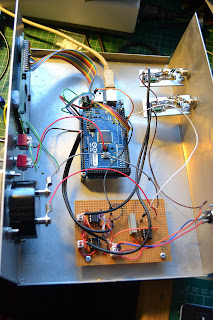
So, here's what I did.... Firstly I ripped the main board out of the box and threw it in the bin. Then I replicated the Sample and Hold op-amp circuitry plus the amp used to drive the meter on some veroboard. This board plus an Arduino

www.arduino.cc

board I had were introduced into the box....


So, I have the original AD8307 boards, but everything else has been replaced. I opened a blank arduino "sketch" (or project) and started from scratch to write the code....

Because the Arduino code is written in a high level language and there are very few memory or other limitations on the board itself, the code doesn't need to be especially well optimised for speed or size. Also the high level language and the library routines that come out of the box mean that all the "tricky" bits associated with reading the AtoD or setting the PWM et cetera are already available for use - so the software is really quite easy to write and also easy to read and modify by other people.

Here's a link to the code:

http://www.qsl.net/g/g0mgx//BlogFiles/power_meter.ino

and also the spreadsheet that I made to calibrate it:

http://www.qsl.net/g/g0mgx//BlogFiles/Power%20Meter%20Calibration%20Arduino.xlsx

So the LCD display is currently set up to display the forward and reflected power in Watts and dbM plus the calculated SWR. The SWR is also indicated on the meter.

The code took an evening to start and then about 6 hours to complete going with my ever favoured method of write a bit, test a bit.


There's lots left still to do, like a front panel and a meter scale. I will also introduce the concept of average power readings and things like that. But I think I need to see the unit in use before I can decide exactly how I want it to behave.

Cat's not impressed:

Good though, egh?

Sunday, 28 October 2012

It's Becoming a Real Power Struggle

Well, blimey!

How hard can it be to get a piece of PIC assembler software to display some characters on an LCD display? The answer seems to be very.

I've started putting my power meter together, it's the one I started here:

http://g0mgx.blogspot.co.uk/2012/10/a-bit-of-power-struggle.html

Well, eventually I managed to assemble all the parts and put the boards into an enclosure I have here:


I've actually made quite a good job of the metalwork so far, I've intentionally not cut the hole for the display as I don't yet know which one of the many I have here I would end up using. Here's the view of the front panel as-is now, the meter looks OK but isn't the large meter I found, as that's just too big for the case!


So, PIC programmed, LCD display wired in, power on - nothing. Just some very faint black squares on the display that I can make more evident or go away using the on-board contrast control.

So, still not knowing if the software is intended to interface to an HD4470 compatible or not, the question was what to try next?

I ended up cutting the software back to just the display routines and simply programming the PIC with the code to display just a few characters on the LCD. Result - nothing.

So, next I added a simple loop at the end of the LCD routine calls to turn on and off one of the digital output ports every second. I attached a suitable LED to the port and tried again - as expected the LED started to flash. This told me a few things:

  • My PIC programming was working and my software was making it into the chip;
  • The software was reaching my loop for LED flashing so it wasn't getting stuck anywhere;
  • The routines for the LCD weren't working.
Now, you may (or may not) recall I did quite a bit of fiddling with LCD displays and Pinguino and more recently Arduino back here:

http://g0mgx.blogspot.co.uk/2012/02/four-isnt-quite-same-as-2.html

So from that messing about I had a reasonably good idea how the initialisation of these LCDs should look, and the code I was staring at didn't quite look the same. So I changed the sequence of numbers sent to the LCD to initialise it, re-programmed the PIC and tried again. Nothing.

Hmm, next I looked at the delays in the software between writing the Enable line on the LCD high and then low again - you kind of have to do an "open sesame" on the LCD every time you send it either data or a command and the delays in the assembly software I was looking at used the processor "nop" instruction. This is really a null operand and hence takes one (I think) clock tick to execute. I changed this to be a 1ms delay and.... Bingo! We have characters on the display:


So, my next puzzle was the fact that I could display the characters 0-9 OK, but any attempt at alpha characters resulted in, what looked very much like, Japanese characters appearing on the display. After much cursing, general muttering and many re-programming of the PIC to try different things, I found a short between two of the address lines on the board. Doh! It took me over 6 hours to find that as I was only looking in software....

So it does seem that I am moving in the correct direction. I have also found that the Assembly code I downloaded from the QST in-depth website for this project, doesn't assemble on my version of MPLAB. I've had to change a few things:

  • declared names are clearly case sensitive in my assembler and not used in that way in the code - many capitalisation changed;
  • literal values used with the "loadw" command - the decimal declarations used generated value too big warnings, all I have done is declare the values as the hex equivalent and prefixed with "0x" - I don't understand why this is different, but it assembles;
  • The declared names in the .inc file for the processor are also case sensitive so again, a number of changes needed there.
I then incorporated my changes to the display routines into the downloaded software and now I am seeing what I expected to see on the display.....

It's time to test the unit, I'll let you know how I get on. I suspect I need to re-make the directional coupler (again) as I posted a photo on the eHam.net homebrew forum and asked for some advice, here's a very polite post telling me what a pile of junk I have made:

eHam comments

Hard work, frustrating but all good though, egh?


Saturday, 19 May 2012

More WSPRing and QRSSing

Well,

After my last ramblings here:

http://g0mgx.blogspot.co.uk/2012/05/back-to-real-homebrewing.html

I've been doing some travelling with work, so progress is not so good. However, I have entered into a dialogue with a number of folk over my observation that the amplitude of the DSS reduces as the frequency increases. Some suggestions to overcome this mainly include AGC type circuitry or utilising pin 12 of the AD9851 to feedback a voltage to set the output amplitude based on a sample of the output (recursion see recursion). The most interesting feedback that I got, however, was not that the amplitude was dropping with an increase in frequency, but that my scope wasn't reading the signals correctly. The theory being that as the frequency increases my scope sensitivity drops off....

I ended up plotting this graph:


This is implying that my scope starts to take a dive, accuracy wise, after about 1MHz, this is the blue line with the y-axis indicating how many dB my scope is "deaf" by. The yellow line is the same signal but through the on-board low pass filter from the DDS module. This seems to imply that the LPF is rather badly designed also. If this theory is correct I need to subtract my scope deafness from the drop in signal out of the LPF. If at this stage we remember that 6dB is half voltage, this is not insignificant!

All rather confusing? My scope is a 100MHz rated fluke which I thought was supposed to be a good quality instrument. So, is this behaviour typical or is my scope a pile of dingos kidneys? I wonder...

I've made a bit of progress boxing the WSPR and QRSS beacon project:


So far, I have tried a number of output amplifiers, the first based on the circuit in my original QRSS beacon, from back in December 2010:

http://g0mgx.blogspot.co.uk/2010/12/qrss-beacon.html

This gives me a nice clean 4v P-to-P voltage out, but I wanted more than that, so either I add another stage or do something else.


I have also tried an output amp based on the Analogue Devices AD8008, this works OK also. I'm off on my travels again tomorrow, so I'll pick this up again when I get back.

All good fun though, egh?

Monday, 27 February 2012

It's Even in a Box Now!

Following on from my previous post; I've been busy boxing my DDS.


I bought a case from my local Maplin, it's the same case as my digital modes interface is boxed in from here:

http://g0mgx.blogspot.com/2011/10/how-come-its-siuch-damn-mess-again.html

I'm totally useless at cutting metal, so a plastic enclosure is the only real option if I want to do this myself, here is the front panel (with the display upside down) taking shape:


And placed into the outer frame:


Some clothes pegs hold it all together whilst the glue sets:


And here it is, finished:


Not bad, egh?

Sunday, 26 February 2012

DDS Running Well

Following on from my previous post I've been playing with the software for the DDS experiments I've been doing. The software is written in C and compiled in the Pinguino IDE and runs on the 4550 Pinguino board I made previously:

http://g0mgx.blogspot.com/2012/01/penguin-you-mean-penguino.html

Ed, EI9GQ, has been inspirational with this and other experiments of mine; his DDS VFO information can be found here:

http://homepage.eircom.net/~ei9gq/dds.html

I've posted a video on You Tube of the results of this recent experimentation here:


If anyone is interested, the source code for this DDS is here:

UPDATE 16/6/2012: I've re-written the code in Arduino (http://g0mgx.blogspot.co.uk/2012/06/its-been-ages.html):

http://www.qsl.net/g0mgx/files/G0MGX_DDS.ino

Fun, egh?

Wednesday, 22 February 2012

Progress is Fast and Furious!

After a bit of a false start with my latest DDS experiments, finally I have made a huge leap forward and made a pile of progress.

I was struggling to get the programming of this AD9851 to work successfully, but after resorting to reading the datasheet all became clear!

The AD9851 modeule is attached to my Pinguino board from my previous post:

http://g0mgx.blogspot.com/2012/01/so-hows-penguin.html

It's connected and setup in serial programming mode so there are actually only 3 connections plus ground between the DDS and the Pinguino PIC. 

The part I was struggling with was the on-board clocking of the AD9851. The older 9850 just runs and the clock speed you attach to it; however the 9851 has a 6X clock multiplier on-board. This small board has a 30MHz clock, so multiplied by 6 should be a clock speed of 180MHz; I wasn't seeing that. However, now I've cracked it and have it configured so that the clock is running at 180MHz.

So I've got the 4 line display running, I've got some test code that sets the DDS output at 5MHz and that's working fine. I know I can get the data entry keypad and the rotary encoder to work OK, so it's just the software now. I say just, hmmm, it may take me quite a while. But at least now I can write a bit of code and test it on this setup with confidence.

At last! It's so frustrating when you are playing with software and hardware - which do you blame. Nothing happening is rather hard to debug. At lest I now have a good solid starting point.

The only other thing I need to look into is the power supply to the AD9851. I've got it powered on the same +5V line as the PIC board, but it's running rather hot. But at least it's functional!

Pinguino rocks!

Saturday, 11 February 2012

Four isn't quite the same as Two!

Firstly I have to report that my work is once again getting very badly in the way of my play time; there's not so much I can do about that if I want to continue to get paid. Therefore I shrug my solders and simply get on with it. Looks like I'm off to Abu Dhabi next weekend with my employer - I tend to travel a lot, but the United Arab Emirates for one day of work, even to me seems rather nuts.

So, in my last post I said that I wanted to use a 4-character display module for my latest DDS experiments; well this has kept me foxed for some time. It got so bad that I actually had to download the manufacturers data sheet and read it! Now that really is desperate!

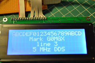
I've got the display working now, it looks rather nice, but as usual is close to impossible to photograph:

But as you can see; I have successfully written to all four lines of the display. As it transpires this LCD module requires exactly the same initialisation as a 2 line module; the trick is in finding the address of the start of each line. They actually wrap so that line 1 feeds onto line 3 and line 2 and 4 proved just impossible to find!

I ended up with commands in hex of 80, C0, 94 and D4 for the start of lines 1, 2, 3 and 4 respectively. All of the code I'm developing to talk to this display is still using the Pinguino board and IDE I made back here:

http://g0mgx.blogspot.com/2012/01/penguin-you-mean-penguino.html

I'm still waiting for my Hong-Kong sourced AD8951 DDS chip, so the actual DDS experiments themselves will have to wait. At least I have some confidence that I can write to my display module of choice!

Cat's not been helping much as usual:


Good though, egh?

Sunday, 15 January 2012

So, how's the penguin?

I've been fiddling with my Pinguino board a little after the build I reported last time. I have, in fact, created a second board - this one will end up as my first Pinguino project. I would like to make a DDS signal generator, but this one needs to include a sweep function so I can more accurately measure crystal filters.

Here's the new board, you'll see that I have interfaced an LCD display, a keypad and if you look carefully you will see there is a rotary encoder there also:

The display has a really neat blue backlight, but is almost impossible to photograph:
I actually want to use a four line LCD display that I have here, I think the software needed to drive the four line display will be the same, I just wanted to start with something I am more familiar with. I am a great believer in build a bit - test a bit.

The keypad will be used for frequency entry, and I have that working OK - I wrote a test program to simply display the keypad entry on the LCD and that's working fine. The shaft encoder will be used to change the frequency steps by utilising the push click switch that's built into it and the rotary part will be tuning when in signal generation mode.

So far so good, but the DDS module I have here I used before:

http://g0mgx.blogspot.com/2011/08/dds-this-and-dds-that.html


This uses a AD9850 DDS chip, and at the time I was interested in the later AD9851 DDS but I couldn't find a way to buy the chip in anything other than the basic SMT package itself. A quick look on eBay suggests that you can now get development boards quite cheaply for this IC now so I have ordered one. It includes 6x clock multiplier on board so it should be easier to get extreme accuracy without spending a fortune on an accurate high stability high frequency clock module.

So, now I wait for a parcel from Hong Kong - why there aren't any in the UK I have no idea.

Time will tell, fun though, egh?

Monday, 9 January 2012

Penguin - you mean Pinguino!

Well,

For a few days I've been playing once again with Pinguino:

http://www.pinguino.cc/

It's an IDE that simplifies programming of PICs and the one I've built uses the 18F4550 PIC from Microchip. The board I have built is detailed here:

http://wiki.pinguino.cc/index.php/PIC18F4550_Pinguino

and it looks like this:


I had quite a bit of difficulty getting the IDE to run on Windows 7; previously I managed to get it running on Linux, but with some help from the Pinguino forum users, I was pointed at this tutorial:


Which has worked out just fine. The IDE is now running:


and this communicates with the board via a Bootloader that you have to program into the PIC. I accomplished this using my recent ebay purchased Olimex PIC board:

This board is directly compatible with the Microchip MPASM IDE and programming the PIC was a doddle.

Once the PIC was programmed and on-board my homebrew Pinguino I have managed to successfully download and run an initial test program to flash an LED. Not much to show for it, but good progress!

I'm planning to play some more with DDS and some other homebrew ideas I have; all of which will be PIC based.

Watch this space!