Search This Blog

Radio Guy Tees

Radio Guy Tees
Radio Guy T-Shirts
Showing posts with label Arduino. Show all posts

Saturday, 23 November 2013

Now that the smoke has settled

Well,

You may remember the mishap I had with my FT-847 back here:

http://g0mgx.blogspot.co.uk/2013/11/my-ft847s-got-no-nose.html

It's been repaired, and as predicted I had melted some of the components in the 4/6M low pass filter. I had also burned some of the PCB tracks - I got lucky really as the PA itself survived.

To further my adventures on 4M Meteor Scatter I think I need to find a better way of generating some high power RF without running the 847 at maximum bananas. Hence a new linear project has been born.

I've scribbled down my thoughts over the design, I want to include some software based control and alarms so I can watch out for:


  • To much drive
  • High SWR
  • PSU problems
  • Over temperature
It would also be good to include a software based power measurement and SWR reading on the output.

Here's the rough starter design:

I've stuck the appropriate numbers into Elsie and have the Low Pass Filter design also:


I've ordered a 300W 50-75 MHz RF module (no PSU, heatsink or cooling) so I'll start to think about the software for the linear controller over the next week or so - it will be Arduino based for sure.

There was a lovely UK morning captured on Antenna Cam here today:

Good, egh?

Sunday, 30 June 2013

Can we do it with less?

Well,

My 30M QRSS Arduino based beacon is still on the air; and I am receiving reports via e-mail from time to time. The most recent was from Andre, DL8WX; he is in JO30WE 716.75 km (445.390 miles), bearing 112.3 degrees from me and said "I found ur beacon last night with a strong signal on 10140.02 kHz for the first time!". The beacon project build is here:

http://g0mgx.blogspot.co.uk/2013/06/qrssing-again.html

Last night, I left my FT-DX-3000 WSPRing on 40M using the dipole I made here:

http://g0mgx.blogspot.co.uk/2013/04/well-further-to-my-musings-last-time.html

and here's the result:


Before I left it alone I measured the power out exactly using my Arduino based power meter from here:

http://g0mgx.blogspot.co.uk/2012/11/the-power-is-with-me.html

and the list of stations heard/hearing looks like this:


So, you have to wonder, if this is achievable with 40dbM (10dBW or 10 watts), what could we achieve with far less power?

Given that the most recent 50mW QRSS beacon project is Arduino based, I could write some software to generate WSPR using that, I would need a GPS to give me an accurate time source, there's also exactly that in a (not quite finished) project from here:

http://g0mgx.blogspot.co.uk/2012/05/more-wspring-and-qrssing.html

or even this Hans Summers project from here will do it exactly as I describe above (GPS and WSPR):

http://g0mgx.blogspot.co.uk/2012/07/qrssing-again.html

So, time to fiddle!

As a slight aside, I'm going to Malta for a week soon and I have 9H3JM for use there; as my FT-450 is in Doha I have bought myself an FT-817 to take with me. This radio is capable of outputting much lower power levels than the other radios I have here, so perhaps the easiest option for some really low power WSPR is to use that?

Lets see.

Friday, 14 June 2013

QRSSing Again

Well,

You may remember way back when I did some mucking about with QRSS (that's really low power slow morse):

http://g0mgx.blogspot.co.uk/2010/12/qrss-beacon.html

I've found another kit from Hans Summers:

www.hanssummers.com

This time it's an Arduino shield - so I can write and fiddle with the software to drive this myself.

Here's the kit as delivered:


it's very simple to make:


and here is the finished thing sat on top of it's Arduino host:


So, a bit of simple software to get the board to send my callsign in FSK QRSS mode, and we now need to align the beacon to be somewhere between 10.140.000 and 10.140.100 - that's quite a narrow band to aim at.

The easiest way seems to be to use the Argo software - it's a kind of spectrum monitoring thingamabob where you can set the offsets associated with the radio connected. So I tuned by FT5000 to 10.139.000 USB (because the carrier offset in USB is 1000Hz) and then entered that as the offset in the Argo software. I then adjusted the beacon to be at what looks like 10.140.060:


I dont really understand why I can see more faded images of the beacon in other parts of the spectrum, but the main beacon seems to be around 10.140.060/065. You can see the end of an "X" and then the start of my call again with a "G" then a "0".

Looking at the output of the beacon on my new Spectrum Analyser thingy, we see this:


The Analyser cant go to an accurate enough frequency, but it confirms that the RF peak is at 10.140 - so I am certainly in the right ballpark and my maths isn't out of bonk.

It looks good and clean on the 'scope too:


Might just take this back with me to A71 land and see what we can see. In the meantime I'll connect this to an antenna and see if anyone can spot me!

Fun, egh?

Friday, 21 December 2012

DDSing once more

Well,

I've been out of the country for a while; been working in the US of A. Great place, visited Chicago, Pittsburgh and Houston this trip - got myself some great boots!

Today I have broken up for Christmas and am looking forward to some good time at home with family, friends and, of course, my hobbies!

I've been fiddling today with the DDS signal generator I made here:

http://g0mgx.blogspot.co.uk/2012/02/dds-running-well.html

And would like to improve the design a little. It would be good to follow the DDS with a broadband RF amplifier, perhaps the one I used here would be a good starting point:

http://g0mgx.blogspot.co.uk/2012/06/its-been-ages.html

Who knows? I would also like to add a stepped output attenuator that's controlled by software and also feedback the RF output to one of the Analogue inputs of the Arduino so I can have a dbM display on the LCD, much like the separate meter I made recently:

http://g0mgx.blogspot.co.uk/2012/11/calibration-complete.html

So, my starting point was to replicate the existing project and then add the AD8307 logarithmic amplifier circuitry:


So here we are again, another project is born.

I'll keep you posted, fun though, egh?

Monday, 12 November 2012

My Power Struggle is Over

Well,

Following all the palaver associated with my Power Meter project; I've finally completed it.

Here's the finished article:


The front panel (which is covered in Fablon) isn't anything like as bumpy as it looks in the photo to the naked eye; it's perfectly acceptable.

I've finally decided that the switches need to switch between short and long sample times (as before) but the second switch that I had used to peak hold the meter, now switches the units primary display units from dbM to dbW - each of these has the power converted to watts in brackets.

The unit had quite a bit of use this weekend in the WAE RTTY contest - and yes I was sending and receiving QTC traffic! - but the meter certainly seems to work at full UK power from my linear, it's a damn site more accurate than anything else I have here, but most impressive was the ability of the unit to read really low reflected powers so I can tune the antenna far better with this unit than I can with any of the analogue meters I have here. This meter can tell be that I have -20dbW reflected power when an analogue meter wont even be moving.... I'm actually quite impressed.

Cat's not overly enthusiastic about it:

Impressive though, egh?


Saturday, 3 November 2012

Scaling the heights of power

Well,

Having finally got a working digital and software based power meter, I have been running some experiments today - already this is proving to be a useful instrument. I think it might be worth making an alternative version of the system to be a stand alone power meter (rather than a directional meter with SWR calcs). However, the main enhancement today has been the inclusion of a (rather humorous) meter scale for the analog SWR meter:


All I did was remove the metal scale that came with the meter, scan it into the computer and then use MS Paint to alter it. I've printed it and stuck it to the old one with "pritt stick". Looks kind of fine to me:


The instrument display is looking pretty good too:


There are two switches on the front panel (as per the W7IEQ design). So I've modified the software to either sample the RF in a short mode or a longer, more time between samples mode. Hence you can see "Sht" for "Short" - this changes to "Lng" or "Long" when the 1st switch is set. Similarly I've added some code to peak hold the meter and this can be turned on with the second switch; the display shows "Norm" or "Hold".

I need to do something better with the front panel of the case and also I'd like to illuminate the meter.


Not bad though, egh?
 

Friday, 2 November 2012

The Power is with me...

Well,

After all the antics with this power meter project, I've finally got a working project; however, not quite through the route you would imagine.

Having spent even more time studying the assembler code for the W7IEQ power meter, and realising that I would need to change all of the vast lookup tables used to convert the AtoD readings into dbM, I then found something in the code comments that made my heart nearly stop...

"This routine uses a packed 16-bit floating point value that I developed to reduce memory usage in a look-up table relating power in watts to measured ADC values for forward and reflected powers.

The packed values contain a 10-bit "reduced" mantissa (m) and a 6 bit shifted exponent (s).  All values are assumed positive so there is no need for a sign bit. Also, the first bit in the mantissa, which is always 1 except when the number id 0, is suppressed.  The offset value for the exponent is 27. A shifted exponent of 0 means the number is 0."

So I very rapidly concluded that I stood little or no chance of getting to grips with this in a hurry, and I was close to despair already with this anyhow!

So, here's what I did.... Firstly I ripped the main board out of the box and threw it in the bin. Then I replicated the Sample and Hold op-amp circuitry plus the amp used to drive the meter on some veroboard. This board plus an Arduino

www.arduino.cc

board I had were introduced into the box....


So, I have the original AD8307 boards, but everything else has been replaced. I opened a blank arduino "sketch" (or project) and started from scratch to write the code....

Because the Arduino code is written in a high level language and there are very few memory or other limitations on the board itself, the code doesn't need to be especially well optimised for speed or size. Also the high level language and the library routines that come out of the box mean that all the "tricky" bits associated with reading the AtoD or setting the PWM et cetera are already available for use - so the software is really quite easy to write and also easy to read and modify by other people.

Here's a link to the code:

http://www.qsl.net/g/g0mgx//BlogFiles/power_meter.ino

and also the spreadsheet that I made to calibrate it:

http://www.qsl.net/g/g0mgx//BlogFiles/Power%20Meter%20Calibration%20Arduino.xlsx

So the LCD display is currently set up to display the forward and reflected power in Watts and dbM plus the calculated SWR. The SWR is also indicated on the meter.

The code took an evening to start and then about 6 hours to complete going with my ever favoured method of write a bit, test a bit.


There's lots left still to do, like a front panel and a meter scale. I will also introduce the concept of average power readings and things like that. But I think I need to see the unit in use before I can decide exactly how I want it to behave.

Cat's not impressed:

Good though, egh?

Friday, 15 June 2012

It's been ages.....

Work, work and more work. That's all there is to it at the moment; finaly, however, I now have some time to:
  1. Catch up with my Blog;
  2. Play some Radio!
The WSPR and QRSS beacon I was begining to develop here:

http://g0mgx.blogspot.co.uk/2012/05/back-to-real-homebrewing.html

is finaly complete!

The output amplifier that I was fiddling with ended up as an Analogue Devices AD8008, which I ended up mounting on a kind of break out board that I had:


You can see how this helps with the "ugly" construction and the use of SMD devices. I can't remember where I got this break out type board from, but it certainly came in useful here!

Many, many moons ago I built myself an QRP ATU, and now I have it permanently hooked up between this beacon and a cheap vertical HF antenna I have slung up against the side of the house. So the setup looks like this:


The WSPR and QRSS beacon is written in C for Arduino:

www.arduino.cc

and I've made quite a few changes to the source code which can be found here in anyone is interested:

http://www.qsl.net/g0mgx/files/Mega_DDS_60_v2_1_G0MGX_eeprom.ino

I've got this hooked up to a GPS module which is sitting in the window of the shack, this is providing the timing data to the WSPR and QRSS beacon. Currently I've got it running on 30M and will be doing some checks for reports in the near future. It's utputting a stagering 20mW!!!!

I've also started (well nearly finided) re-writting the code for my recent DDS project in Arduino; I was never quite happy with the way that ended up, so using my new found C skills I have written (from scratch) the DDS control software.

The original project is here:

http://g0mgx.blogspot.co.uk/2012/02/dds-running-well.html

The functionality is the same as before, it's just that it works better and I have a much better understanding of how it works.

The source code for this is here:

http://www.qsl.net/g0mgx/files/G0MGX_DDS_FINAL.ino

I can claim some originality in this one!

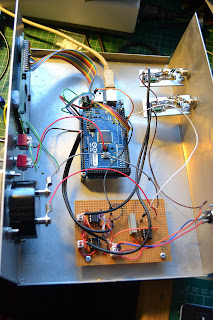
Here's the inside of the replacement DDS, you can see that it's now Arduino based:


Please excuse the clothes pegs; they are just holding bits in place whilst the glue dries. I'll post again about this piece of work once completed. It's kind of soak testing right now as there is a calibration routine included to adjust the DDS for any misalignment in the frequency output due to clock inaccuracies.

All good though, egh?

Monday, 7 May 2012

Back to real homebrewing!

You may recall my discovery back here:

http://g0mgx.blogspot.co.uk/2012/04/well-this-looks-just-great.html

So, Ive managed to make some progress. I've modified the software from W3PM from here:

http://www.knology.net/~gmarcus/

and have managed to get the GPS module working and also the DDS drive routines....


The code is written in C for the Arduino; and it's now interfaced to a four-line LCD, the AD9851 DDS module and the GPS receiver. The GPS module isn't in the picture as it's hanging out the window so it has visibility to the sky.


I've started to box the project, and have also built an RF amp to get me a staggering 100mW out...


Progress has been quite good today, I need to think about how I can get the RF levels the same on each band because as the frequency increases, so the amplitude out of the DDS and hence out of the RF amplifier decreases. I'm really not sure how to tackle that one, so I may have to ask for some help here.

Yesterday myself and Vince G0ORC went over to the "Dambusters Rally":


The rally was really good, albeit a bit small, but there was loads of really good radio junk to rummage about in. I picked up all sorts of stuff including this meter which I am rather proud of:


I've cleaned it up, mounted it on some wood, and stuck it in the corner of the shack with some amps flowing through it...


The next step will be to put some lighting inside...

Looks god though, agree?

Thursday, 12 April 2012

Extreme Soldering (DDS-60) Complete!

It seems that the extreme soldering is complete for another project! The DDS-60 I got from AmQRP is built.

I've found that photographing the soldering and then inspecting it blown up is about the best way I have found for checking the integrity of SMT soldering. Here is the complete board (top and bottom):


But when you actually look at the soldering blown up, it's quite a mess! I don't think there are actually any problems or shorts though:


Tomorrow or over the weekend I'll be testing this....

Fun, egh?

Wednesday, 11 April 2012

It's extreme soldering again!

Well, I've started with my Arduino WSPR beacon project from here:

http://g0mgx.blogspot.co.uk/2012/04/well-this-looks-just-great.html

I've hit some obstacles with the GPS module and am planning to come back to that bit later.

The original plan that I am going to follow uses an American QRP Club project the DDS-60.

http://midnightdesignsolutions.com/dds60/index.html

This is a AD9851 based DDS but includes a small on-board RF amplifier and a low pass 60MHz filter. As this was the board used in the design, I ordered one. It arrived today and looks like this:


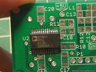
It's another surface mount project and came very neatly packaged. I had to purchase the AD9851 separately (I think when the kit was originally put together you could get a sample from Analogue Devices). Now, this AD9851 is a very small component indeed and has 28 pins... Using a suitable soldering iron and a magnifying glass I have managed to get the chip on the board OK. This is the best I can manage to show the result:


If you open up the image above you can see that it's not a bad job. Here's the other SMD chip installed:


So the rest should be quite easy going in comparison as they are just Rs and Cs....

All in all not a bad start to the latest exercise in extreme soldering.. not bad, egh?

Thursday, 5 April 2012

GPS Time Sync? How's That Work Then?

I've made a bit of progress with the latest project that I mentioned here:

http://g0mgx.blogspot.co.uk/2012/04/well-this-looks-just-great.html

It's this project here for WSPering using the Arduino development board and the Analogue Devices DDS 9851 chip I've been experimenting with:

http://g0mgx.blogspot.co.uk/2012/02/its-even-in-box-now.html

So, I've got the Anduino board:


And have just soldered together the GPS module to get the timing information:


So I have no idea how to interface to this GPS module, but I have an extended Easter weekend to try and find out. There seem to be loads of reference pieces of code on the Internet for almost anything you could think of, so I'm sure I'll think of something.

Here's the Geddy cat, he really isn't helping much today:


Not such a great shot, but here's where the bed is (out of reach of the pesky Chopsy cat):
Fun, egh?

Sunday, 1 April 2012

Well, This Looks Just Great!!!!

Not much been happening here recently; the job is getting badly in the way.

Been WSPRing on 6m over the past few days; the results are rather dull but there are some interesting peaks in propagation across the UK.


I've been rummaging on the Internet and happened to stumble across this:

http://www.knology.net/~gmarcus/

This is a really neat project combining the Arduino technology (similar and a Cousin of Pinguino - well Pinguino is an off spring of Arduino) and the AD9851 DDS that I have been playing with recently.

I've just gotta build one!

So I've found the Arduino board in my local Maplin and the DDS boards I already have should work in this application so it's soon to be play time!

Here's the obligatory cat photo:

Watch this space!