Search This Blog

Radio Guy Tees

Radio Guy Tees
Radio Guy T-Shirts

Friday, 26 April 2013

Baluns, Baluns, Baluns - what's that about?

Well,

Following my initial musings on the topic of baluns back here:

http://g0mgx.blogspot.co.uk/2013/04/a-what-un-ah-balun.html

I've run a simple test here today to try and see what, exactly, is going on with this commercial balun I have here. It's a BU-50 manufactured by Diamond Antennas (cost about 30 GBP).

As I stated before, I expected to feed a signal into this balun and see two signals 180 degrees out of phase with each other on the output (when measured against the input ground). Starting at about 500KHz, here's what we see:


So, this is pretty much as I expected. The yellow and blue lines are the two outputs - they are very close to being 180 degrees out of phase. The green smudge in the middle is the sum of the two signals - this is the effective cancellation effect we expect in the balanced feedline as they cancel each other out. Looking at it another way, if we subtract the two signals, we should get close to the original input, which we do:


So, the next thing I did was to start to increase the frequency of the input signal, here at 1.5MHz:


There is a noticeable reduction in the phase difference in the two signals at 1.5MHz, but I guess it's still close as the summation of the two (green) is still very close to nothing. Now, I increased the signal to 6MHz:


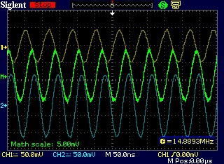
Then to 15MHz:


and finally, to 30MHz:


So, by the time we get to 30MHz, the signals seem to be considerably out of bonk - that technical expression means "not as expected".

What does this all tell me (Other than I need to go out more)? Not sure yet - the next thing to try is to wind some low power baluns myself and compare results. I certainly don't think this commercial balun is going to do what it's supposed to do across the HF spectrum.

Odd, egh?

60M Test - Seems OK to me!

Well,

Following the modification to the FT-DX-3000 to give the ful 60M allocation in the UKhere:

http://g0mgx.blogspot.co.uk/2013/04/your-going-to-what.html

I left the radio WSPRing on the 5MHz band last night.

Seems OK to me:


What do you recon, good egh?
 

Thursday, 25 April 2013

Your going to what?

Well,

You may recall that I bought myself a FT-DX-3000 recently, this is a great radio but I decided I needed to add the narrow roofing filter. I bought said component and prepared to take the radio to bits:


There are a total of 18 screws holding the base of the radio on, once you have all of these removed the inside looks like the photo below. I have drawn a black box round the empty slot for the narrow filter and also added a red arrow which we will discuss further down. Here's the radio without the filter fitted:


and again with the filter in place:


Now, whilst I had the radio in pieces, I thought I would wideband the TX. This is because I want to be able to use the radio on the 5MHz UK allocation including the WSPR frequencies. The full allocation isn't available as-is, so the only option is to perform the full wideband TX anywhere mod.

The picture above with the black box also has the red arrow, underneath the part of the radio with the red arrow pointing looks like this close up:


In the top of the photo you will see that there are 9 numbered points on the board, two of which (6 & 7) are populated with 0 ohm SMT resistors or more simply links.

To wideband the FT-DX-3000, you have to bridge the pads number 5. Here is the radio with the modification complete:


You have to perform a FULL reset for the change to take effect (hold down fast & lock then power on).

Simple, egh?

Monday, 15 April 2013

A what-un? ah, A Balun!

Well

Whilst musing about being able to run SO2V or SO2R back here:

http://g0mgx.blogspot.co.uk/2013/04/so2v-so2-what-ah-2-vfos.html

there are quite a few things to consider. If I am going to operate with 2 radios at the same time, the most important factor will be protecting the radio in receive from the high RF generated by the radio in transmit - this could result in some very expensive damage if not catered for correctly - more on this later.

The other thing I need to accomplish is a second antenna for the higher bands. Lets say I want to run on 20M and 15M at the same time, clearly I can use the MA5B on one radio, but I don't currently have a second antenna for either of these bands. The simplest solution (as very much a starter for 10) is to cut and hang up a simple common multiband antenna - a G5RV. I've cut one using some hard drawn copper wire I had here, some 450 ohm ladder line and a commercial balun...... hence the confusion and lack of understanding.

I've always been bothered by baluns - what do they do and how do they do it? Whats the difference between a current balun and a voltage balun - whats a 4:1 balun for? Whats a 9:1 balun for? Why don't I just go out more and not worry?

Over the coming weeks I plan to run some experiments to answer these questions, to run some tests against a commercial 1:1 balun, and to construct some baluns for myself and see what they actually do.

So, starting with the newly strung G5RV which I've included a commercial balun between the 450 ohm feedline and the coax to the shack, I see this with my newfangled antenna analyser thingamabob:


Now, I only plan to really use this antenna connected to a second radio, but as a starter for 10, the antenna looks like it's OK ish. As a quick test (clearly the SWR on my dummy load will be better!) I left the antenna and radio WSPRing on 30M last night:


So, I conclude that the antenna radiates and it looks like I can transmit a signal using it.... so it's not just a dummy load. This is a good start.

So, the next project will be some kind of band stop filters for the radios so certain radios can only be used on certain bands - this should allow me to experiment with SO2R in an RTTY contest.

Now, back to baluns.... A balun should be used where we go from a balanced arrangement (e.g. a dipole) to an unbalanced arrangement (e.g. coax cable). I would therefore expect that the output of the two balanced ports of a balun would be out of phase with each other when compared to the ground point of the input port. Here I am feeding a 10MHz signal into a commercial balun and measuring the two terminals of the balanced output:


So, the yellow and the blue (please ignore amplitude) are the two output ports and the green is the sum of the two signals.... they look to me to be about 45 degrees out of phase - this is not what I was expecting at all! I thought they would be 180 degrees out of phase such that the sum of the two was as close to zero as makes no odds.

Unfortunately (or fortunately, depending on how you look at it), I'm heading back to A71 land again today.... I'll be picking this up in about two weeks when I get back.

I'd like to hear from anyone who understands the 'scope output above though, confusing - egh?

Thursday, 11 April 2013

My antennas got no nose; well no decent SWR anyhow!

Well,

Further to my musings last time about SO2V, I've been making some changes here with a view to getting a second HF general purpose antenna up in the air - the idea being that this can be connected to the second V!

I took down the 30M (10MHz) dipole that I had here and put up a half size G5RV - this was something I had kicking around anyhow and it's fed with 400 Ohm ladder line. It's good and clear and up quite adequately high. I was rather horrified and/or surprised to find that signals on 40M were way stronger on this G5RV than on my 40M/80M dipole - something was not right!

So here's what I did:
  • Checked the antenna SWR to find it close to infinite everywhere....
  • Replaced the feedline (RG213) between the shack and the ground level under the dipole centre.
  • Replaced the feedline (RG58) between the end of the RG213 and the dipole centre.
  • Checked the SWR with the analyser at the end of the RG58 feeder and there is a clear SWR curve around 7 MHz ish
  • Then checked the SWR at the shack end of the RG213 cable and its 10:1 flat….
  • Went for a curry
  • Decided to look again at the dipole centre so I dropped the antenna again
  • Centre looked OK, so tried to pull the antenna back up and broke the bailing twine in the pulley at the top of the pole at the bottom of the garden
  • Gave up completely and went to bed 

Today I've replaced the pole at the bottom of the garden and made an alternative antenna, here is the design I came up with:


The inductors ("L") in the design calculate out at about 80uH.

The first thing I did was to just construct the two 33' legs of the antenna and get them tuned to the RTTY/Digital segment of 40M - that was a doddle. Then I added the coils and the stubs, the calculation was aimed at 3.050MHz and here (using my new fancy analyser thingamabob):


So not bad at all! Here's the plot for 40M now I've added the stubs - clearly there has been some slight de-tuning of the 7MHz part of the antenna, but I can live with it for now and fiddle some more with it later:


The only other thing I have to report was that following my being a good boy at work I have bought myself a gift:


The picture doesn't do the radio justice; it's quite nice looking and has a shiny finish (not the normal Yaesu matt). The good things are that the radio includes a CW decoder, plus in-built decoding for PSK and RTTY - you can also send all three modes without any external equipment.

All in all I think it will be an excellent second radio for me - it has replaced the TS-590 - too early to report fully but early signs are good!

Fun, egh?

Monday, 8 April 2013

SO2V - SO2 What? Ah, 2 VFOs!

Well,

During a two day break from work, I've been fiddling about with Writelog and Logger32 (the programs I use for RTTY) to try and experiment with the 2 receivers I have in the main FT-DX-5000 here.

The idea being that I can have:
  1. Main receiver to an MMTTY decoder providing the main RX window
  2. A clone of the main receiver window running an alternative decoder (2Tone)
  3. The second receiver on the same or a different band into a third decoder running either/or MMTTY and 2Tone.
So far, In logger32 I have achieved everything I set out to do:


I have the two receivers in the radio, both with frequency read from the radio correctly and the ability to receive in both 2Tone and MMTTY on both.

Now, in WriteLog I almost have the same thing:


But not quite! I have two receivers feeding two versions of MMTTY with the main receiver also having a clone using 2Tone. What I can't get to work is reading the receiver frequency of the 2nd receiver within the radio. Eventually, of course, I would like to be able to TX back to a signal received on either receiver i.e. TX on the main or sub receiver frequency; I suspect that may be asking just a bit too much, although I think it's possible if I had two separate radios, so I dont see why not...

I'll keep trying, I wonder if anyone else has this set-up working?

Complex, egh?
 

EA RTTY Test

Well,

Home from A71 land for a week and had a bit of a dabble in the EA RTTY contest, here is the now obligatory map from the log, not sure why I have grids on the map, but hey ho:

Good though, egh?