
Well,
You may recall some time ago that I had a fiddle with a Red Pitaya? This was back here in this post.
So further to the WSPR RX I was doing back then, I made a request via Mike Richards G4WNC (He writes the Data column in Practical Wireless) to add a PTT switch to the software. The TX signal was on the output connector and the RX input on the Input connector - I only have one antenna and I wanted to switch between the two.
Well, lo and indeed behold, the code for the Multiband WSPR transciever has been updated here.
I've downloaded the new software which includes an extra module called gpio-output which switches the DIO0_P pin (its pin 3 on the E1 connector) to 3.3V when the device is in TX.
Now, I noted a few things when I downloaded the new files and executed the make command:
To accommodate this I have made a very simple PTT switch (please excuse my TinyCad capability):
 which connects to the Red Pitaya Pin 3 and GND on the E1 connector and then feeds a PTT line (grounded during TX) to my TX/RX relay.
The only Relay I had was a latching type so I have made a board from W6PQL to drive the relay from a grounded line:
This board looked like this when I had it under test:

And this is what the latching signal looked like before I added some diodes on the relay coils:

Now, you may remember that I also purchased a board from SV1ASM to add some extra drive to the Red Pitaya output, here it is under test:


And here we have the 'scope connections to the output connector and the E1 lines:

So, hooking all this lot together, we have a mess like this:

I need to make a low pass filter for the output; mine is currently configured to TX on 30M. Once I have the LP filter I will stick this on the air and see how far I can hear and be heard.
This project is now a good starting point for lots of other TX/RX type ideas on the board.... next though I think I am going to have a go at the Vector Network Analyser.
Here's Florrie the Ham cat being almost completely in the way throughout:

Good egh?
You may recall some time ago that I had a fiddle with a Red Pitaya? This was back here in this post.
So further to the WSPR RX I was doing back then, I made a request via Mike Richards G4WNC (He writes the Data column in Practical Wireless) to add a PTT switch to the software. The TX signal was on the output connector and the RX input on the Input connector - I only have one antenna and I wanted to switch between the two.
Well, lo and indeed behold, the code for the Multiband WSPR transciever has been updated here.
I've downloaded the new software which includes an extra module called gpio-output which switches the DIO0_P pin (its pin 3 on the E1 connector) to 3.3V when the device is in TX.
Now, I noted a few things when I downloaded the new files and executed the make command:
- The Makefile downloaded ended up with a .1 extension and needed to be renamed.
- The new .sh files had the wrong permissions and needed to be chmod ed to be executable
To accommodate this I have made a very simple PTT switch (please excuse my TinyCad capability):
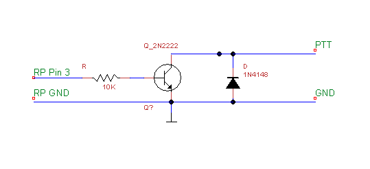
The only Relay I had was a latching type so I have made a board from W6PQL to drive the relay from a grounded line:
This board looked like this when I had it under test:

And this is what the latching signal looked like before I added some diodes on the relay coils:

Now, you may remember that I also purchased a board from SV1ASM to add some extra drive to the Red Pitaya output, here it is under test:

Now, this is supposed to give me about 14dB of gain, but my tests suggest it's a bit short. The Tracking Generator is at -20dB in the test below:

It may just be that I am not driving it hard enough in the test above, as I am getting more like 7dB gain. It seems to be good to about 100MHz though - I will look more at this later.
Before I hooked all this stuff up together, I did some tests on the Red Pitaya output lines. This 'scope screen grab is showing the TX output plus the IO line at 3v3 during TX:

And here we have the 'scope connections to the output connector and the E1 lines:

So, hooking all this lot together, we have a mess like this:

I need to make a low pass filter for the output; mine is currently configured to TX on 30M. Once I have the LP filter I will stick this on the air and see how far I can hear and be heard.
This project is now a good starting point for lots of other TX/RX type ideas on the board.... next though I think I am going to have a go at the Vector Network Analyser.
Here's Florrie the Ham cat being almost completely in the way throughout:

Good egh?


