Search This Blog

Radio Guy Tees

Radio Guy Tees
Radio Guy T-Shirts

Friday, 6 December 2013

Wow - that's Windy!

Well,

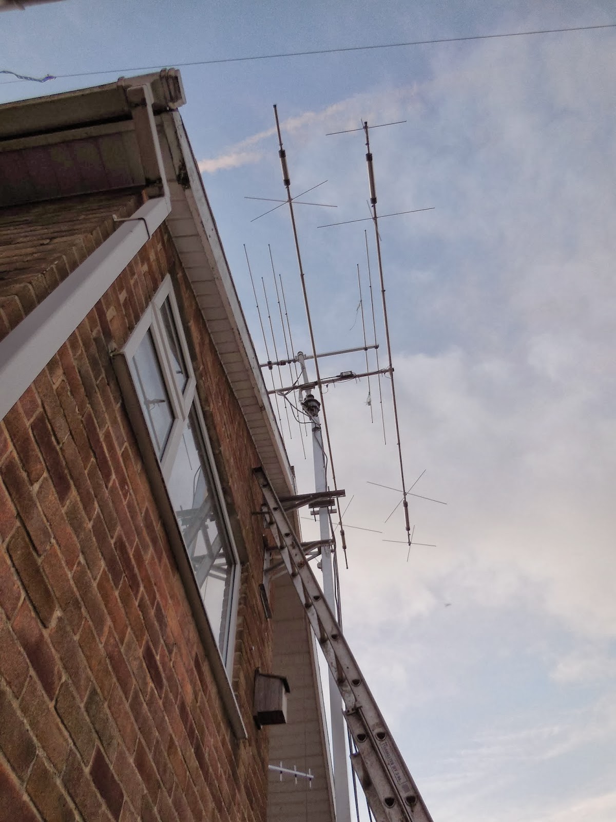
We had quite a storm in the UK yesterday; luckily I wasn't at home to witness it else I would have been in a real panic I would imagine! Anyhow, the winds were extreme to say the least and this morning I look up at the main antenna and I see this:


The top of the mast is at a definite angle compared to the rest of it, so I turned the antenna to the West - this is the direction I point it when I want to tip it over - looking up again once it was turned that way and everything looked fine! Hmmm, something not so clever here. I started to drop the tower and the antennas all started turning as gravity wanted them to. It seemed that the stub mast to the rotator from the main mast was no longer attached to the square section at all!

Here's what I found when I brought the tower down:


So the three bolts I used as part of the re-engineered top of the tower from back here:

http://g0mgx.blogspot.co.uk/2012/08/changes-at-top.html

have snapped clean off. The power of the wind is amazing.

So I've put it back together with some suitable modifications; hopefully this won't happen again.

Scary, egh?

Wednesday, 4 December 2013

Lindy is up in the Air!

Well,

Remember the antenna I was describing back here:

http://g0mgx.blogspot.co.uk/2013/12/whos-lindenblad-i-wonder.html

I've finished it and stuck it up in the air:


The antenna analyser thingamabob suggests that the actual resonant point of the antenna is about 149MHz, but the SWR at 145.9 MHz is still only 1.4:1.

If I stick the antenna on the RLB I started to make here:

http://g0mgx.blogspot.co.uk/2013/09/return-loss-bridge-where-does-it-lead.html

Then this is what we see:


I explained the trace we see above using the Return Loss Bridge with the Spectrum Analyser back here:

http://g0mgx.blogspot.co.uk/2013/10/so-lets-get-bit-smarter.html

So there is a definite resonate point at 150.7Mhz, but there is also a very good match at 144.5MHz, at my target frequency of 145.9 the SWR is 1.38:1 which is perfectly acceptable.

Whilst I have been up and down ladders today, the cat has been completely useless as per normal:


Fun, egh?

Tuesday, 3 December 2013

70MHz Linear - Progress is Steady!

Well,

You may recall the Linear Amplifier I mentioned I was going to make back here:

http://g0mgx.blogspot.co.uk/2013/11/now-that-smoke-has-settled.html

And I was testing the Low Pass Filter for the output stage here:

http://g0mgx.blogspot.co.uk/2013/12/low-pass-looks-more-wobbly-to-me.html

Well, I've completed the main amplifier module and it's mounted on a suitable aluminium pallet which in turn is mounted on a heatsync.


Now that I have this main part of the linear, I can begin to build the peripheral components in my favourite way; build a bit, test a bit.

Watch this space.

Who's Lindenblad I wonder?

Well,

Since the launch of the new cubesat Funcube-1:

http://funcube.org.uk/

I've been watching the path of the satellite while I've been in the shack (tracking it with logger32) and downloaded telemetry data on a number of the birds passes using the funcube dashboard (available on the link above).

I've only been using a vertical "white stick" that I have on the side of the house, and the antenna is far from optimum for listening to Low Earth Orbiting Satellites (LEOs).

So, I did some research and found this:

http://n3ujj.com/manuals/Lindenblad-2meters.pdf

This is an easy to construct Lindenblad antenna - designed specifically for LEOs reception. Now, "easy to construct" for me was not so easy. Anyhow, I ordered the metal I needed and some other bits and bobs and today I have been to see my friend Paul who has a metal workshop. He has helped me cut, bodge, bend, hit and rivet stuff. I've brought all the bits home and assembled something that looks like this:


So what we basically have is four dipoles all slightly non-resonant such that they present a 200 ohm impedance so when they are connected together we end up with a 50 ohm antenna.


The feeder arrangement is rather odd; the pdf linked above suggests soldering the four cables into the N-Type socket but that looked as near to impossible as makes no odds so me - I'm trying this bodged arrangement first!


I'm just off to get the "corporate" antenna analyser that covers 144MHz - then we will see if I have created an antenna or a clothes line of some sort.

Cat's been no use whatsoever today:


Interesting, egh?

WSPRing on 80M - Shhhhh

Well,

You may recall the new antenna that I made back here:

http://g0mgx.blogspot.co.uk/2013/12/80m-into-43-feet-that-doesnt-go.html

So to try and get some idea of the performance I left my TS-590 WSPRing on 80M last night. Here is what I find this morning:


And here closer view without the VK station:


So, focusing on that VK contact I had a look in the WSPR database and this is what I find:


So that doesn't even look like the appropriate times for a greyline propagation contact; interesting.

Here is the actual heard/hearing list for last night:


Whilst a great deal of the work is being done in software, it certainly suggests that the antenna is both radiating well and also hearing well.

What do you reckon? Good, egh?

Monday, 2 December 2013

Low Pass - Looks More Wobbly to me!

Well,

You may recall the basic ideas for a 4 and 6M linear that I discussed back here:

http://g0mgx.blogspot.co.uk/2013/11/now-that-smoke-has-settled.html

I've started to fiddle with the software and have most of the basics working. The software will just about control everything in the amplifier including cooling and alarms. The most important alarm will be the over drive - I suspect even with input attenuation I am going to find it very easy to overdrive the amp.

I started a few days ago to make the low pass filter. My first attempt looked kind of OK and used air cored inductors, but when I hooked it up to the spectrum analyser and tracking generator I didn't like what I saw at all:


The overall response wasn't very flat and at the target frequency I had quite a bit of attenuation. As a consequence and thinking it was my inductors that were suspect I ordered some T50-10 torroids as these would be good at 70MHz and also would create the required inductances with a reasonable number of turns.

The Low Pass Filter design has evolved a little bit and now looks like this in theory:


So after the T50-10s duly arrived a re-wound all the inductors only to find exactly the same result. Hmmm.

So, then I tried:

  • Winding Air Cores with a smaller inside diameter
  • Reducing the capacitor values and adding trimmers so I could fiddle with the filter
  • Going for a curry
None of the above helped much, the results were still rather rubbish at my target frequency i.e. I had buckets of attenuation where I didn't want any.

Then I tried using some different test leads:


Conclusion? The test leads I was using are spectacularly rubbish at 70MHz - Aaarrrghhhh!!!!

I do have a slight bit of attenuation at my target frequency - the slope is starting just a little too soon, and I need to decrease the capacitors either side of the center inductor a tad.

So here's the filter as built right now:


So I can only conclude that the first attempt at the filter was fine, I just didn't know! The moral of this story is to always connect the test leads from the Tracking Generator output to the Spectrum Analyser input without the circuit under test in the way to ensure you have a flat line - do this first!

Here's the ham cat:


Annoying, egh?

Sunday, 1 December 2013

80M into 43 feet - That doesn't go!

Well,

I've been looking around for some time for some means of getting a signal onto 80M. I thought about creating something like the inductive antenna I made for top band back here:

http://g0mgx.blogspot.co.uk/2012/08/top-band-what-happens-there-then.html

But I found this link the other day, and this looked like it was worth a go:

http://www.sral.fi/turva/G7FEKantenna.pdf

The antenna looks like this:

So we have both sides of the open wire feeder connected to the centre of the coax feed and the antenna itself fed against ground.

I've taken down the 10MHz dipole I had up in the air and made one of these and put it in it's place. The open wire feeder comes down rather close to the house but it's all fitted OK:


On the earth or counterpoise side I have attached 60' of copper wire which ambles it's way along the ground down the garden and then across the bottom of the plot. I've also dug out a set of cut counterpoise wires I made to take to Malta with me and attached them and strung them out in the flower beds also.

I've just been listening to a DK5 caling CQ and he is an S3 on the windom I have from here:

http://g0mgx.blogspot.co.uk/2013/08/so-who-is-caroline-ah-carolina-windom.html

and S9 on this new antenna.

Only time will tell, but initial signs are promising.

This cant be a comfortable place to sleep, can it?


Fun though, egh?