
Well,
After all the antics with this power meter project, I've finally got a working project; however, not quite through the route you would imagine.
Having spent even more time studying the assembler code for the W7IEQ power meter, and realising that I would need to change all of the vast lookup tables used to convert the AtoD readings into dbM, I then found something in the code comments that made my heart nearly stop...
"This routine uses a packed 16-bit floating point value that I developed to reduce memory usage in a look-up table relating power in watts to measured ADC values for forward and reflected powers.
The packed values contain a 10-bit "reduced" mantissa (m) and a 6 bit shifted exponent (s). All values are assumed positive so there is no need for a sign bit. Also, the first bit in the mantissa, which is always 1 except when the number id 0, is suppressed. The offset value for the exponent is 27. A shifted exponent of 0 means the number is 0."
So I very rapidly concluded that I stood little or no chance of getting to grips with this in a hurry, and I was close to despair already with this anyhow!
So, here's what I did.... Firstly I ripped the main board out of the box and threw it in the bin. Then I replicated the Sample and Hold op-amp circuitry plus the amp used to drive the meter on some veroboard. This board plus an Arduino
www.arduino.cc
board I had were introduced into the box....
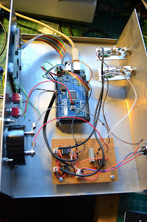
So, I have the original AD8307 boards, but everything else has been replaced. I opened a blank arduino "sketch" (or project) and started from scratch to write the code....
Because the Arduino code is written in a high level language and there are very few memory or other limitations on the board itself, the code doesn't need to be especially well optimised for speed or size. Also the high level language and the library routines that come out of the box mean that all the "tricky" bits associated with reading the AtoD or setting the PWM et cetera are already available for use - so the software is really quite easy to write and also easy to read and modify by other people.
Here's a link to the code:
http://www.qsl.net/g/g0mgx//BlogFiles/power_meter.ino
and also the spreadsheet that I made to calibrate it:
http://www.qsl.net/g/g0mgx//BlogFiles/Power%20Meter%20Calibration%20Arduino.xlsx
So the LCD display is currently set up to display the forward and reflected power in Watts and dbM plus the calculated SWR. The SWR is also indicated on the meter.
The code took an evening to start and then about 6 hours to complete going with my ever favoured method of write a bit, test a bit.

There's lots left still to do, like a front panel and a meter scale. I will also introduce the concept of average power readings and things like that. But I think I need to see the unit in use before I can decide exactly how I want it to behave.
Cat's not impressed:
 Good though, egh?
After all the antics with this power meter project, I've finally got a working project; however, not quite through the route you would imagine.
Having spent even more time studying the assembler code for the W7IEQ power meter, and realising that I would need to change all of the vast lookup tables used to convert the AtoD readings into dbM, I then found something in the code comments that made my heart nearly stop...
"This routine uses a packed 16-bit floating point value that I developed to reduce memory usage in a look-up table relating power in watts to measured ADC values for forward and reflected powers.
The packed values contain a 10-bit "reduced" mantissa (m) and a 6 bit shifted exponent (s). All values are assumed positive so there is no need for a sign bit. Also, the first bit in the mantissa, which is always 1 except when the number id 0, is suppressed. The offset value for the exponent is 27. A shifted exponent of 0 means the number is 0."
So I very rapidly concluded that I stood little or no chance of getting to grips with this in a hurry, and I was close to despair already with this anyhow!
So, here's what I did.... Firstly I ripped the main board out of the box and threw it in the bin. Then I replicated the Sample and Hold op-amp circuitry plus the amp used to drive the meter on some veroboard. This board plus an Arduino
www.arduino.cc
board I had were introduced into the box....

So, I have the original AD8307 boards, but everything else has been replaced. I opened a blank arduino "sketch" (or project) and started from scratch to write the code....
Because the Arduino code is written in a high level language and there are very few memory or other limitations on the board itself, the code doesn't need to be especially well optimised for speed or size. Also the high level language and the library routines that come out of the box mean that all the "tricky" bits associated with reading the AtoD or setting the PWM et cetera are already available for use - so the software is really quite easy to write and also easy to read and modify by other people.
Here's a link to the code:
http://www.qsl.net/g/g0mgx//BlogFiles/power_meter.ino
and also the spreadsheet that I made to calibrate it:
http://www.qsl.net/g/g0mgx//BlogFiles/Power%20Meter%20Calibration%20Arduino.xlsx
So the LCD display is currently set up to display the forward and reflected power in Watts and dbM plus the calculated SWR. The SWR is also indicated on the meter.
The code took an evening to start and then about 6 hours to complete going with my ever favoured method of write a bit, test a bit.

There's lots left still to do, like a front panel and a meter scale. I will also introduce the concept of average power readings and things like that. But I think I need to see the unit in use before I can decide exactly how I want it to behave.
Cat's not impressed:

One question…why to use a sample and hold ?
ReplyDeleteI mean, in arduino you can decide when to check the ad8307 with a specific period of time BUT really do you need an external S/H ?
FANTASTIC YOU CATS!!!!
Only just seen this comment - sorry. I'm not sure its really necessary but I wanted to ensure that the forward and reflected samples were taken at the same time.
ReplyDeletegood evening, I did EXACTLY the same thing with this pic power meter, only thing good it did for me way make me learn to program a pic the correct way HA
ReplyDeleteregards, Chuck - KA1MWP (see my site)
I have just started gathering parts to the original Project, but I see some of the parts are really hard to get hold on. Your approach looks MUCH better, so is it possible to get some more details, schematics etc.
ReplyDeleteBesrt regards
LA2SL Ulf
hi I am in the process of creating a db meter using the AD8307 chip and uno . could you perphase give me a wiring diagram of how to wire up the chip with mic and Uno ?
ReplyDeleteDrop me an email and I can send you a detailed schematic.
DeleteMark (good at QRZ.com)
Good Morning Mr. Mark
ReplyDeletevery good your project, it would be possible to share the same?
Forgive me for daring to ask him.
Very good to see your project completed. I found the story of your travails on eHam. I'm just about to start this project.
ReplyDelete