Search This Blog

Radio Guy Tees

Radio Guy Tees
Radio Guy T-Shirts

Monday, 18 June 2012

FT-847 on 4M or 70MHz

The FT-847 that I have here includes the 70MHz band when you sequence through using the band up and down button; it also excludes the more recently allocated 7.1MHz to 7.2MHz at the top end of 40M. The latter doesn't bother me too much.

The RF out on 70MHz is a mere 10W, and I have recently been reading about a mod to increase this safely.

The details of the mod have been published by G4FUF here:

http://www.70mhz.org/847mods.htm

The first step is to remove the outer casing by taking off the carry handle and other associated screws, then we need to confirm a number of jumper settings and then measure some test points:


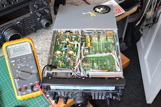
this is to confirm that the on-board configuration is as it needs to be. The test points are in this area of the upper board:


Then the lower board needs to be moved out of the way, this is a simple task by removing 4 gold screws and flipping the board towards the front of the radio:


This provides access to the PA, but first the shield has to be removed:


 Then, finally, we have access to the PA:


Then a piece of ferrite needs introducing into the centre of L5006; this will bring the resonance down to below the 70MHz band.

****** IMPORTANT ******

It is essential that the correct type of core is used otherwise excessive heating may occur; you cant just use any piece of ferrite! The core needs to have a relatively low mu and should be a VHF/UHF type. The core from a TOKO S18, MC120 or MC122 are usable and are currently available from JabDog:
www.jabdog.com


****** EVEN MORE IMPORTANT *******

There's a better way:

http://g0mgx.blogspot.co.uk/2012/06/ft-847-pa-mod-theres-better-way.html

*************************


You can see the modified component right in the centre of the photo here:


Once this is complete, it will have initially made no difference at all!
We also need to remove the ALC mod that is still restricting the output on 70MHz, this is completed by snipping the green wire in the image below (this is the top board in the radio):


Now I have the desired 65W (ish) out on 70MHz. I've ordered a pre-amp kit to improve the radio on RX, I'll post more when it arrives.

Good though, egh?

Friday, 15 June 2012

It's been ages.....

Work, work and more work. That's all there is to it at the moment; finaly, however, I now have some time to:
  1. Catch up with my Blog;
  2. Play some Radio!
The WSPR and QRSS beacon I was begining to develop here:

http://g0mgx.blogspot.co.uk/2012/05/back-to-real-homebrewing.html

is finaly complete!

The output amplifier that I was fiddling with ended up as an Analogue Devices AD8008, which I ended up mounting on a kind of break out board that I had:


You can see how this helps with the "ugly" construction and the use of SMD devices. I can't remember where I got this break out type board from, but it certainly came in useful here!

Many, many moons ago I built myself an QRP ATU, and now I have it permanently hooked up between this beacon and a cheap vertical HF antenna I have slung up against the side of the house. So the setup looks like this:


The WSPR and QRSS beacon is written in C for Arduino:

www.arduino.cc

and I've made quite a few changes to the source code which can be found here in anyone is interested:

http://www.qsl.net/g0mgx/files/Mega_DDS_60_v2_1_G0MGX_eeprom.ino

I've got this hooked up to a GPS module which is sitting in the window of the shack, this is providing the timing data to the WSPR and QRSS beacon. Currently I've got it running on 30M and will be doing some checks for reports in the near future. It's utputting a stagering 20mW!!!!

I've also started (well nearly finided) re-writting the code for my recent DDS project in Arduino; I was never quite happy with the way that ended up, so using my new found C skills I have written (from scratch) the DDS control software.

The original project is here:

http://g0mgx.blogspot.co.uk/2012/02/dds-running-well.html

The functionality is the same as before, it's just that it works better and I have a much better understanding of how it works.

The source code for this is here:

http://www.qsl.net/g0mgx/files/G0MGX_DDS_FINAL.ino

I can claim some originality in this one!

Here's the inside of the replacement DDS, you can see that it's now Arduino based:


Please excuse the clothes pegs; they are just holding bits in place whilst the glue dries. I'll post again about this piece of work once completed. It's kind of soak testing right now as there is a calibration routine included to adjust the DDS for any misalignment in the frequency output due to clock inaccuracies.

All good though, egh?

Saturday, 19 May 2012

More WSPRing and QRSSing

Well,

After my last ramblings here:

http://g0mgx.blogspot.co.uk/2012/05/back-to-real-homebrewing.html

I've been doing some travelling with work, so progress is not so good. However, I have entered into a dialogue with a number of folk over my observation that the amplitude of the DSS reduces as the frequency increases. Some suggestions to overcome this mainly include AGC type circuitry or utilising pin 12 of the AD9851 to feedback a voltage to set the output amplitude based on a sample of the output (recursion see recursion). The most interesting feedback that I got, however, was not that the amplitude was dropping with an increase in frequency, but that my scope wasn't reading the signals correctly. The theory being that as the frequency increases my scope sensitivity drops off....

I ended up plotting this graph:


This is implying that my scope starts to take a dive, accuracy wise, after about 1MHz, this is the blue line with the y-axis indicating how many dB my scope is "deaf" by. The yellow line is the same signal but through the on-board low pass filter from the DDS module. This seems to imply that the LPF is rather badly designed also. If this theory is correct I need to subtract my scope deafness from the drop in signal out of the LPF. If at this stage we remember that 6dB is half voltage, this is not insignificant!

All rather confusing? My scope is a 100MHz rated fluke which I thought was supposed to be a good quality instrument. So, is this behaviour typical or is my scope a pile of dingos kidneys? I wonder...

I've made a bit of progress boxing the WSPR and QRSS beacon project:


So far, I have tried a number of output amplifiers, the first based on the circuit in my original QRSS beacon, from back in December 2010:

http://g0mgx.blogspot.co.uk/2010/12/qrss-beacon.html

This gives me a nice clean 4v P-to-P voltage out, but I wanted more than that, so either I add another stage or do something else.


I have also tried an output amp based on the Analogue Devices AD8008, this works OK also. I'm off on my travels again tomorrow, so I'll pick this up again when I get back.

All good fun though, egh?

Monday, 7 May 2012

Back to real homebrewing!

You may recall my discovery back here:

http://g0mgx.blogspot.co.uk/2012/04/well-this-looks-just-great.html

So, Ive managed to make some progress. I've modified the software from W3PM from here:

http://www.knology.net/~gmarcus/

and have managed to get the GPS module working and also the DDS drive routines....


The code is written in C for the Arduino; and it's now interfaced to a four-line LCD, the AD9851 DDS module and the GPS receiver. The GPS module isn't in the picture as it's hanging out the window so it has visibility to the sky.


I've started to box the project, and have also built an RF amp to get me a staggering 100mW out...


Progress has been quite good today, I need to think about how I can get the RF levels the same on each band because as the frequency increases, so the amplitude out of the DDS and hence out of the RF amplifier decreases. I'm really not sure how to tackle that one, so I may have to ask for some help here.

Yesterday myself and Vince G0ORC went over to the "Dambusters Rally":


The rally was really good, albeit a bit small, but there was loads of really good radio junk to rummage about in. I picked up all sorts of stuff including this meter which I am rather proud of:


I've cleaned it up, mounted it on some wood, and stuck it in the corner of the shack with some amps flowing through it...


The next step will be to put some lighting inside...

Looks god though, agree?

Friday, 4 May 2012

Why is this just so insane?

Well, in a recent post I mentioned that the 2m/70cm beam antenna here had decided that once horizontal it didn't want to work so well. It was OK when I used it for satellite operation at 28 degrees, but when we put it back to horizontal the SWR went through the roof. I managed to take the head of one of the grub screws that allow you to adjust the gamma match - so that wasn't too handy either. Anyhow, as an antenna for conventional SSB working it's not going to be much cop, as it's a real compromise for both bands.... so......

I bought a 7 element ZL special from moonraker for 144MHz:

http://www.moonraker.eu/

and it duly arrived a few days later.

Now I am no real antenna expert; my understanding of antennas is that you attach a piece of wire to the inside of a length of coax, place the wire on something nearby that's handy - maybe a hedge or something - then you work the world on HF.... not so on VHF!

There were two confusing aspects to this antenna for me; firstly there are two driven elements (which are actually folded dipoles) and the directors (elements) are not ordered smallest to biggest from the front of the antenna to the dipoles. Hmmmm.....

The two dipoles are fed at 180 degrees out of phase with each other, here you can see the main feedpoint which contains the coax from the radio, a piece of 300 ohm ribbon cable which feeds the other folded dipole and a tuning "stub" - this is in effect an open length of RG58:


These two folded dipoles are sightly different sizes, presumably this offers a broader bandwidth to the antenna tuning point.

Having struggled the pole back down, me and the ever patient Vince G0ORC, we had the new antenna mounted ready to go back up in the air:


You can see the 6m beam and also the new 2m ZL special:


We tuned the antenna on the ground; you chop small bits of the end of the open "stub" for best SWR. It seems to be quite straightforward, once up in the air the SWR was perfect in the SSB portion of the 2m band:


So, the antenna is back in the air, the SWR is near perfect and we could hear PI7CIS all the way from JO22, the directivity of the antenna seems quite sharp, so something is working OK!

Fun, egh?

Friday, 27 April 2012

6m Beam Swap

I decided I should swap the 6m beam that I have up here. A number of reasons for this decision, firstly everyone round here seems to have got used to it being there, so an mysterious increase in size one dark and stormy night was probably going to go un-noticed. Secondly the SWR on the old antenna is not so good.

This 3 element beam came from Lam Communications in Barnsley:

http://www.lamcommunications.net/shop/

I believe it's actually a Sandpiper antenna:

http://www.sandpiperaerials.co.uk/

It went together really easiy and is much sturdier constructed than the two element beam I was using:

http://g0mgx.blogspot.co.uk/2011/05/6m-and-counting.html

The new antenna has gone up OK, it's a bit trickier to lift past the eaves of the house and attach to the pole (thanks to the ever patient Vince, G0ORC) it's in place.

We altered that the beam antenna I had pointing upwards for satellite working to be horizontal. In the process of doing this we wrecked the SWR and lost some of the grub screws from the Gama match. Hey, ho - that's another story.

Here's the new 6m antenna:


Good egh?

It's nearly over (Until the next time)

Well,

After changing the bench last time:

http://g0mgx.blogspot.co.uk/2012/04/even-more-change.html

I've finished finishing the desk (if you get what I mean). I've added some trim to the edge and it's finished it off rather well. Having done that (of course) I then decided that I should stain and wax the shelves to match. Whilst that bit's quite easy; the replacing the shelves without removing any of the equipment was harder. You've seen the trick of removing the tablecloth and leaving the china on the table - it was a bit like that!


The cat seems to approve of the new bench, he stopped of here en-route to his favourite napping position:


Looks ok though, don't ya think?