Search This Blog

Radio Guy Tees

Radio Guy Tees
Radio Guy T-Shirts

Saturday, 30 June 2012

Even More 4M or 70MHz

I've been fiddling in the shack today with an oscilator I started back here:

http://g0mgx.blogspot.co.uk/2012/06/4m-70mhz-and-counting.html

It's basically an 20MHz crystal oscilator that's multiplied up to 80MHz. I've then fed that into a mixer just like the one used in the BITX here:

http://g0mgx.blogspot.co.uk/2010/12/bitxing.html

And mixed it with the 10MHz reference oscilator I made here:

http://g0mgx.blogspot.co.uk/2011/07/ocxo-oh-you-mean-ocxo.html

The idea being that 80MHz - 10MHz = 70MHz.

There are a couple of amplifier stages in there followed by a (my attempt at) band pass fiter. The iportant thing with mixers is that you get the sum, the difference and all sorts of other harmonic products out, so you have to really filter out the one you want else you just get a real mess!

It all looks rather badly built and like this:


But the output on the spectrum analyser looks like this:


So you can see that the 70MHz signal is the main "feature" in the ouput (It's 10MHz per cm from left to right where the far LHS peak is 0MHz and it's also 10db per cm vertically).

I think I will re-make this with consideration for all the bits and where they need to be; then I'll think about seeing if this will make a transmit converter for 4M.

Good fun, egh?

Friday, 22 June 2012

FT-847 PA Mod - there's a better way!

Well,

Following the mod of the PA filter in my FT-847 here:

http://g0mgx.blogspot.co.uk/2012/06/ft-847-that-i-have-here-includes-70mhz.html

I've been thinking some more about this; given that the PA is capable of delivering 100W on 6M or 50MHz, it wasn't clear to me why I Was struggling to get more than about 60W out on 4M or 70MHz. There had to be some very large inefficiencies in there; then I discovered this link:

http://www.70mhz.org/847filters2.pdf

And all became very clear, very quickly! I don't know what package Marc used, but he has done a fine job. Once again the FT-847 came apart and I kept removing bits until I had discovered the PA board:


Now, to make the mod described by PA1O, Marc, I need to lift the PA board out. This was a bit scary as I had to remove all the screws holding the MOSFETs onto the heatsync and then very gently flip the board over. Once upside down, I could clearly see the two caps described in the article:


Then with rather a lot of brute force and ignorance I managed to get the one cap removed; it's been stuck down rather firmly so it kind of came off in bits with no hope of ever putting it back again!


So, after carefully putting it all back together (including a dab or two of heatsync compound), the radio is back together. I've removed the ferrite I added when I did the previous mod:

http://g0mgx.blogspot.co.uk/2012/06/ft-847-that-i-have-here-includes-70mhz.html

And I now have a full 85 - 90 Watts out on 70MHz with about 16A current draw and still have 100W output n 50MHz with a reduced current draw of 17A (it was about 21A); so I think we can conclude that efficiency is improved.

I can't see any negative side effects of this modification to the PA, the output seems stable on all bands but I'll be sure to let you know if I find out differently.

I'm going to look at the output spectra a some point in the near future to make sure the signal is nice and clean and all harmonics are suitable suppressed.

Cat's not impressed:


Good though, egh?

Thursday, 21 June 2012

FT-847 Pre-Amp Installation

So, now that I have built and done the basic DC test on the new FT-847 pre-amp last time:

http://g0mgx.blogspot.co.uk/2012/06/ft-847-4m-70mhz-pre-amp-mod.html

It's time to install the board in the Radio. This looks to be a fairly straightforward operation, replacing one board for another.

Here is the old "daughter" board inside the radio just prior to removal:


And this is the gap - this picture was taken to ensure I could remember where the old board wired into the main board - re-fitting being the reverse of removal!


So here is the new daughter board which includes the 70MHz pre-amp just being tacked into place:


And here with the wiring complete:


All I need to do now is find a suitable signal and peak the variable inductor for maximum smoke; that should be a doddle. I can hear the relays operating as the tuning range enters and leaves the operating frequencies, so something is working as planned.

Not bad, egh?

Wednesday, 20 June 2012

FT-847 4M (70MHz) Pre-Amp Mod

As I mentioned in my last post here:

http://g0mgx.blogspot.co.uk/2012/06/4m-70mhz-and-counting.html

I had bought a mod for the FT-847 to improve the reception on 4M (70MHz). The kit is made by G4FUF and is really quite a neat package which you start with the surface mount components:


Once all the SMD parts are on the board there are a number of inductors:


followed by a pair of relays and an rf connection or two:


So next is to perform a basic DC test and then install inside the FT-847...

Watch this space!

Tuesday, 19 June 2012

4m (70MHz) and Counting....

Following on from the mods I undertook on my FT-847 here:
http://g0mgx.blogspot.co.uk/2012/06/ft-847-that-i-have-here-includes-70mhz.html

I've bought and put up a 4M beam. I've not got it so it can be rotated, nor is it very high off the ground, but it's pointing to the SE and ready for those Es!


So, the house looks like this from the side:


So here you can see a 6M, 2M and now a 4M beam, a vertical for 2M, 70cm and 6M plus the centre of the Windom. The main HF antenna is on the back of the house.

My next project will be a 4M pre-amp for the FT-847 which I have already bought as a kit:


This kit is from Keith, G4FUF, he seems to be the font of all knowledge on the FT-847 and converting it for 4M. I'll post more about this when I make the kit and install it in the radio.

I've also started to think about WSPR on 4M and have just built a 60MHz local oscillator which I could use to mix with a 10MHz signal to get onto 70MHz. All just thoughts at the moment:


Cats not been helping much, as usual:


All good fun though, egh?

New Toy! AKA Old scope vs. New scope

Well, my birthday a little while ago and I decided to treat myself to a new toy. I've been thinking about a digital scope for a while as whilst my Fluke is excellent, I would like the ability to store and remember waveforms; taking pictures of the screen is tricky!

Anyhow, I was concerned about the quality of the waveforms I was seeing on this new scope, so I posted a cry for help on the GQRP forum, as usual I had some very helpful advise. Here is the video I compiled to demonstrate the problem:


Now, I showed the video to the guy I bought the scope from, he seemed to very much share my concerns. He offered to bring some other 'scopes to the house so we could try some side by side to try and find what the problem was. Really  very kind and helpful offer. We did this and agreed on a course of action and I was a happy bunny waiting for another scope to arrive in a week or two.

Anyhow, I failed completely to believe that a digital scope could really be this poor at displaying a sinewave! So first I tried reading the manual, that didn't help much, so I then reverted back to the old tried and tested method of pressing buttons and seeing what happened. Here are my findings:


Good, egh?

Monday, 18 June 2012

FT-847 on 4M or 70MHz

The FT-847 that I have here includes the 70MHz band when you sequence through using the band up and down button; it also excludes the more recently allocated 7.1MHz to 7.2MHz at the top end of 40M. The latter doesn't bother me too much.

The RF out on 70MHz is a mere 10W, and I have recently been reading about a mod to increase this safely.

The details of the mod have been published by G4FUF here:

http://www.70mhz.org/847mods.htm

The first step is to remove the outer casing by taking off the carry handle and other associated screws, then we need to confirm a number of jumper settings and then measure some test points:


this is to confirm that the on-board configuration is as it needs to be. The test points are in this area of the upper board:


Then the lower board needs to be moved out of the way, this is a simple task by removing 4 gold screws and flipping the board towards the front of the radio:


This provides access to the PA, but first the shield has to be removed:


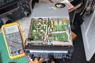
 Then, finally, we have access to the PA:


Then a piece of ferrite needs introducing into the centre of L5006; this will bring the resonance down to below the 70MHz band.

****** IMPORTANT ******

It is essential that the correct type of core is used otherwise excessive heating may occur; you cant just use any piece of ferrite! The core needs to have a relatively low mu and should be a VHF/UHF type. The core from a TOKO S18, MC120 or MC122 are usable and are currently available from JabDog:
www.jabdog.com


****** EVEN MORE IMPORTANT *******

There's a better way:

http://g0mgx.blogspot.co.uk/2012/06/ft-847-pa-mod-theres-better-way.html

*************************


You can see the modified component right in the centre of the photo here:


Once this is complete, it will have initially made no difference at all!
We also need to remove the ALC mod that is still restricting the output on 70MHz, this is completed by snipping the green wire in the image below (this is the top board in the radio):


Now I have the desired 65W (ish) out on 70MHz. I've ordered a pre-amp kit to improve the radio on RX, I'll post more when it arrives.

Good though, egh?

Friday, 15 June 2012

It's been ages.....

Work, work and more work. That's all there is to it at the moment; finaly, however, I now have some time to:
  1. Catch up with my Blog;
  2. Play some Radio!
The WSPR and QRSS beacon I was begining to develop here:

http://g0mgx.blogspot.co.uk/2012/05/back-to-real-homebrewing.html

is finaly complete!

The output amplifier that I was fiddling with ended up as an Analogue Devices AD8008, which I ended up mounting on a kind of break out board that I had:


You can see how this helps with the "ugly" construction and the use of SMD devices. I can't remember where I got this break out type board from, but it certainly came in useful here!

Many, many moons ago I built myself an QRP ATU, and now I have it permanently hooked up between this beacon and a cheap vertical HF antenna I have slung up against the side of the house. So the setup looks like this:


The WSPR and QRSS beacon is written in C for Arduino:

www.arduino.cc

and I've made quite a few changes to the source code which can be found here in anyone is interested:

http://www.qsl.net/g0mgx/files/Mega_DDS_60_v2_1_G0MGX_eeprom.ino

I've got this hooked up to a GPS module which is sitting in the window of the shack, this is providing the timing data to the WSPR and QRSS beacon. Currently I've got it running on 30M and will be doing some checks for reports in the near future. It's utputting a stagering 20mW!!!!

I've also started (well nearly finided) re-writting the code for my recent DDS project in Arduino; I was never quite happy with the way that ended up, so using my new found C skills I have written (from scratch) the DDS control software.

The original project is here:

http://g0mgx.blogspot.co.uk/2012/02/dds-running-well.html

The functionality is the same as before, it's just that it works better and I have a much better understanding of how it works.

The source code for this is here:

http://www.qsl.net/g0mgx/files/G0MGX_DDS_FINAL.ino

I can claim some originality in this one!

Here's the inside of the replacement DDS, you can see that it's now Arduino based:


Please excuse the clothes pegs; they are just holding bits in place whilst the glue dries. I'll post again about this piece of work once completed. It's kind of soak testing right now as there is a calibration routine included to adjust the DDS for any misalignment in the frequency output due to clock inaccuracies.

All good though, egh?